K. Flöttmann, S.G. Wipf
DESY, Notkestr. 85, 22603 Hamburg, Germany
The productions of positrons in sufficient quantities is one of the necessities for either the TESLA or the S-Band Linear Collider project. One of the promising possibilities is to guide the high energy electron beam through a superconducting helical undulator producing synchrotron radiation which would in turn be directed onto a target for positron production [1,2]. To generate sufficient radiation for this purpose from an undulator with inner radius of 2mm and a 14mm period, an on-axis radial field of at least 0.8 T would be required. Calculations were carried out to ascertain whether this field was attainable and what effect the addition of iron in between the superconducting coils would have. An arrangement with iron helices interleaved with helical current coils and a cylindrical yoke for the return flux was optimised. With a current density of 900 A/mm2 and a period length of 10mm, fields of up to 1.3 Tesla were calculated. The increased fields obtained lead to a possible reduction in the overall length of the structure and more flexibility in the choice of electron beam and undulator parameters.
A helical undulator has two advantages compared to a planar wiggler:
The energy of the primary electron beam can be lower, since high photon
energies can be reached with a short period, high field device. Whereas
a source with a planar wiggler can only operate with a minimum beam energy
of at least 150GeV, a source with a helical undulator may be operated down
to an energy of 100-120GeV. In addition the photons of a helical undulator
close to the radiation axis are circularly polarized. Highly polarized
positrons can be generated if the outer part of the photon beam is scraped
off. Thus the same helical undulator could be used for the production of
positrons [2] with a low polarization (30 %) at lower
beam energy (120GeV) and for highly polarized positrons (60%) at high beam
energies (![]() 250GeV).
250GeV).
A helical field can be produced by a pair of conductors wound to form a double helix as sketched in Figure 1. The current in the two conductors is equal and flows in the opposite direction. Thus the central axial magnetic field is canceled and a transverse field pattern appears. The field on the z-axis is approximated by:
![]() (1)
(1)
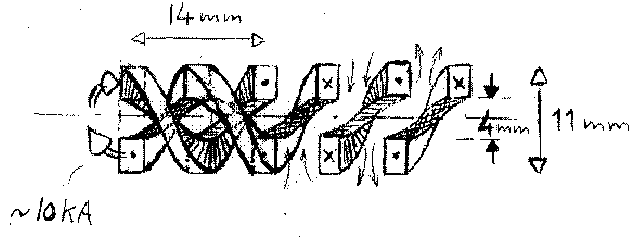
Figure 1 Diagram of an iron free helical undulator. (Picture courtesy of S.L. Wipf.)
An analytical formula for an iron free undulator was derived by Blewett and Chasman [3] as:
![]() (2)
(2)
An on-axis field amplitude, B, of 0.9T is reached when the current
density, I = 900A/mm2, the undulator period ![]() =12mm,
the coil inner radius, ri = 2mm , the outer radius ro
= 6.8mm. A width of 1/3
=12mm,
the coil inner radius, ri = 2mm , the outer radius ro
= 6.8mm. A width of 1/3![]() is assumed for the conductor of the coil.
is assumed for the conductor of the coil.
In order to include the effects of iron magnetostatic calculations were carried out using the numerical code MAFIA [4]. The problem was discretised in a cylindrical coordinate system with 230 000 mesh points. As a first step the analytical result was checked without the addition of iron. The agreement was better than 98 %.
First a double helix of iron was included between the conductors. Figure 2 shows the undulator with the filaments simulating the conductors and the double helix of iron. The on-axis field was increased by about 50%. Next the undulator was enclosed in a return yoke, which gave another 50% in field amplitude. A variation of the current density between 600 and 900 A/mm2 revealed no significant limitation due to saturation of the iron. Since the yield of the positron source depends on both the period and field of the undulator, the period length was reduced to 10mm before the optimization of the geometry. A bore radius of 2mm was chosen, the current density was fixed at 900A/mm2.
A cross-section of the upper half of a helical undulator with the double helix of iron between the coils and a return yoke is shown in Figure 3.
A two dimensional model in x-y coordinates of an equivalent planar wiggler was used for the preliminary optimization of the coil height, coil width and yoke height. Although this is rather far from the actual helical geometry, the results were reasonable enough to provide the starting parameters for the 3D optimization. A model was then chosen, using the most promising 2D configuration as a starting point.
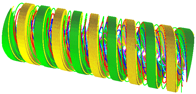
Figure 2 Solid model of the undulator as it is used in the numerical calculations with current filaments and iron between the conductors.
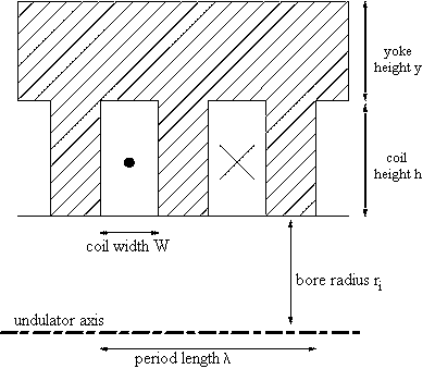
Figure 3 Cross-section of an undulator with iron between the conductors and return yoke (shaded area).
For the three dimensional calculations the current in the superconducting coils has to be distributed among a number of filaments. Very careful discretisation and placing of these filaments was necessary to ascertain the effect of varying the coil height and width. The mesh had to be exactly adjusted so that no variation of current occurred close to the axis as this would have an additional effect on the on-axis field, even though the integrated current density was the same.
The radial on-axis field Br as a function of the coil height h is shown in Figure 4. The field depends strongly on h up to about 4mm after which the curve begins to level off.
A coil height of 5.5mm was chosen with a yoke height of 5mm, then a coil width of 2.8mm produced a definite optimum. Varying the yoke height, y, from 3-7mm had very little effect on the on-axis Br field, even though there was considerable saturation. The maximum permeability in the yoke, varied between 30 and 50.
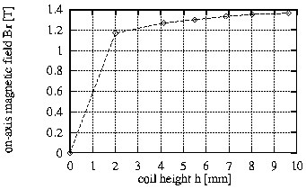
Figure 4. Radial magnetic field amplitude Br as function of the coil height h with constant inner radius ri of 2mm.
Table 1 summarizes the optimized undulator parameters. For comparison the parameters of an undulator with equal period but without iron are given.
Table 1 Optimized parameters for an undulator with iron in comparison with an iron free undulator. The current density is 900 A/mm2.
|
|
|
|
|
|
|
|
|
|
|
|
|
|
|
|
|
|
|
|
|
|
|
|
|
|
|
|
* At this coil height the on axis magnetic field reaches 90 % of the field of a coil of infinite height.
The magnetic field is increased by more than a factor of 2 due to the iron and the optimized geometry. These parameters enable the length of the undulator to be reduced from 150 m for the iron-free undulator to 100 m.
The maximum current density that can be reached in a superconducting cable depends on numerous parameters, such as the copper to superconductor ratio, the number of strands and the winding density, the insulating material, the manufacturing process, the magnetic field at the cable and the temperature. Therefore the maximum current density cannot be determined without a detailed technical design of the magnet. The small bending radius favours the use of thin bands as cable. Due to the strong dependence of the field on the radius one might try to obtain the highest current density close to the undulator axis. We have restricted our calculations to a current density of 900A/mm2, based on the experience with the HERA magnets. The maximum field at the conductor, that limits the allowable current density, is found to be only 2.9T. Recent developments in the field of fabrication techniques [5] indicate considerable improvements in the tolerable current density especially at low fields. With a higher current density both the undulator period and the overall length could be further reduced. For a period of 8mm, a current density of 1700A/mm2 is necessary to reach the desired field of 1.5T. This undulator would allow the operation of the positron source to start with an electron energy of 100GeV. A different approach would be to increase the bore radius of the undulator in order to facilitate the construction and the operation of the device. Increasing the bore radius from 2mm to 2.5mm, while leaving all other parameters as presented in Table 1, would require a current density of 1500A/mm2 for a field of 1.3T. In this case the field at the conductor is 3.2T. These current densities are attainable with modern NbSn conductors.
The radial on-axis magnetic field of an undulator with the specified dimensions is a purely harmonic function of the longitudinal coordinate. No contributions of higher harmonics could be resolved within the resolution of the simulations. Figure 5 shows the radial field amplitude as function of the radial position in comparison with an analytic result for an iron free undulator [3] and a simplified analytical formula which approximates the field of the iron loaded structure given by [3]:

![]() ,
B0 = on-axis field amplitude (3)
,
B0 = on-axis field amplitude (3)
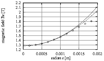
Figure 5 Radial magnetic field as function of the radius (diamonds) in comparison to the field of an iron free undulator (solid line) and a simplified approximation (dashed line).
Particles close to the axis move on helical trajectories with a radius r given by:
![]() (4)
(4)
where ![]() is the cyclotron radius of the particle in the field B0.
is the cyclotron radius of the particle in the field B0.
For a 250GeV electron the radius r is 4nm at a field of 1.3T. Off-axis particles move through a somewhat higher field with an additional field gradient. The trajectory becomes an elliptical helix with eccentricity ~12% for an offset of 1mm.
The radiation of an helical undulator is circularly polarized only near
the radiation axis, while radiation emitted at angles larger than
~1/![]() is
transversely polarized. In order to be able to scrape off the transversely
polarized radiation it is necessary that the electron beam is focused through
the undulator onto the conversion target, so that the spot size of the
radiation on the target is dominated by the opening angle of the radiation.
This requires, besides an excellent beam emittance of the order ~10-10
is
transversely polarized. In order to be able to scrape off the transversely
polarized radiation it is necessary that the electron beam is focused through
the undulator onto the conversion target, so that the spot size of the
radiation on the target is dominated by the opening angle of the radiation.
This requires, besides an excellent beam emittance of the order ~10-10
![]() m, that no focusing occurs within the undulator. The tracking calculations
show that the natural focusing of the undulator is so weak that it can
be completely neglected for the positron source.
m, that no focusing occurs within the undulator. The tracking calculations
show that the natural focusing of the undulator is so weak that it can
be completely neglected for the positron source.
The trajectories in the helical undulator are, however, strongly influenced by the edge field at the entrance of the undulator. Nonlinear kicks can occur if the field is not properly designed.
In the tracking simulations the end field was modeled by a tapered onset of the field given by:
![]() (5)
(5)
With this end field only a dipole kick of ~0.4 µrad occurs at the entrance of the undulator which can easily be compensated. No detailed calculations of the real end field of the undulator have been performed since the end field is closely connected to the technical design of the undulator. The calculations show, however, that the nonlinearity of the kick at the entrance of the undulator can be sufficiently reduced, if the end field is appropriately tapered.
We would like to thank W. Decking who provided the code for the tracking calculations.
1 V.E.Balakin, A.A.Mikhailichenko 'The Conversion System for obtaining high polarized electrons and positrons', Preprint INP 79-85, 1979.
2 K.Flöttmann, 'Investigations Toward the Development of Polarized and Unpolarized High Intensity Positron Sources for Linear Colliders' DESY 93-161, Nov. 1993.
3 J.P.Blewett, R.Chasman 'Orbits and fields in the helical wiggler' Journal of Applied Physics, Vol.48, No.7, July 1977.
4 The MAFIA Collaboration 'Users's Guide MAFIA Version 3.2' CST GmbH, Lauteschlägerstr. 38, 64289 Darmstadt, Germany.
5 R.M.Scanlan et al 'Evaluation of APC NbTi Superconductor in a Model Dipole Magnet' IEEE Trans. on Magnetics, Vol.30, No.4, July 1994.