Secondary electron monitor using longitudinal rf-modulation
of low energy secondary electrons, with initial energy in eV range,
for bunch phase distribution measurement of electron linac bunches
with subpicosecond resolution is considered. Analysis of limiting
resolution for this method, construction particularities of the
monitor, and specific example of its design for the measurement
of the TTF linac beam will be presented.
Development of electron linacs demands creation of a bunch length monitor with subpicosecond resolution that is equivalent to the measurements in frequency domain up to 1 THz or in submillimetre wave range. The monitor has to be compacted, selfcalibrating, unpertubing a beam, compatible with UHV, radiation resistive.
Several approaches are known for solving this challenge.
One of them consists in estimation of the rms bunch length through
two beam current harmonics assuming, for example, bunch charge
distribution is Gaussian [1] or using single harmonic [2] closed
to the rms frequency of a beam spectrum where its amplitude is
most sensitive to the bunch length changes. For the Gaussian bunch
the rms bunch length s
can be determined from equation
where in, im are beam current harmonics unknown precisely. Hence, the technique needs some one to calibrate it.
Method of interferometry of coherent radiation and the others closed to it [3,4] are restricted by wave lengths being more than beam diameter or hole diameter of screen[5].
The use of incoherent radiation, for example, on a scheme: Cherenkov radiator plus a streak camera [6,7], is mainly limited due to the longitudinal chromatic aberration in the camera gap (photocathod - mesh distance) caused by initial velocity spread of photoelectrons. In plane-parallel geometry of the gap one can expect the limiting resolution till 1 ps [8].
In the paper the secondary electron monitor coming up to the above mentioned requirements more completely is presented. (The monitor based on the delta-rays is presented at this Conf. too)
It should be noted that in the best work [9] on research
of time dispersion of SEM (the gap voltage was 3.6 kV) it was
measured, in fact, its longitudinal chromatic aberration only,
and the SEM time dispersion for metal is within 1...10 fs [12].
Secondary electron monitor for bunch phase
distribution (BPD) measurements with subpicosecond resolution
is schematically shown in Fig.1.

Here BPD of a primary beam (1) in a result of the beam interaction with a carbon fibre (2) under negative potential (U0) is isohronously transferred into the same distribution of secondary electrons which, then, is coherently transformed into transverse one in the plane of multichannel collector (6) through rf-modulation in the gap of toroidal resonator (3) and magnet (5) allowing direct presentation the BPD on a low frequency display. Taking into account that the beam diameter is rather small (of 1...2 mm) and the smaller h-distance the less time transport spread (of the electrons) the carbon target was placed from the resonator at small fixed distance h = 2 mm, and this monitor unit is moved in the beam for a time of measurements only.
The monitor phase resolution (Dj)
is mainly defined by the time transport spread (Dj1)
of the electrons on h-distance (2 mm), the shutter phase
resolution (Dj2)
[10] and the additional phase dilution (Djq)
caused by the beam space charge effect. Then, considering the
above mentioned quantities as the independences one can estimate
Dj using
known algorithm from [10].
Time transport spread of the secondaries (Dt)
at their motion in the field of charged cylindrical electrode
under potential -U0 on h-distance (Fig.1,b) until the
conducting wall (A-A) was obtained by numerical simulation using
relativistic equations and taking for the electrons emitted from
carbon their initial energy and angular distributions from [11].
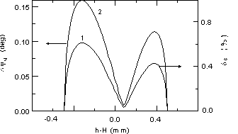
Results of this calculation are presented in Fig.2, where fW
and ft are the initial energy distribution and temporal
one in the plane A-A, respectively, for h = 5 mm, U0
= 8 kV and 2R0 = 0.1 mm. FWHM of ft is 0.227
ps that corresponds the time transport spread of two electrons
with initial energies of 0.335 eV and 3.925 eV if they would move
along the z axis.

In Fig.3,4 are shown the dependencies of the FWHM
of ft (Dt)
vs. the electrode radius and voltage, respectively.


The case of very large R0 (more 100 mm
at small h) corresponds the plane - parallel geometry similar
to the accelerating gap (from a photocathod to mesh) in a streak
camera [6,7]. One can see that using the plane - parallel geometry
and voltage up to 20 kV and higher it is impossible to reach t
= 1 ps or less at input electron size of more several tenth mm.
These results are closed to one published in [8]. For our monitor
R0 = 0.01 mm, U0 = 8 kV, h = 2 mm and t
= 30 fs, i.e. 0.014° in deg. of 1.3 GHz.
Beam space charge effect is the main one limiting
the monitor resolution. Dependencies of the additional phase dilution
(Djq)
and momentum spread (dq)
caused by the effect vs. the target place relative to the beam
axis are plotted in Fig.5 for the geometry of the primary converter
mentioned above and for the next beam parameters: electron energy
- 10 MeV; beam radius - 0.5 mm; bunch length in phase
of 1.3 GHz - 1.5; bunch population - 3108. For
calculation the ellipsoidal bunch with uniform density was taken.
Charges induced by the beam on the target surface was not taken
into account.

For the maximum values of Djq,
dq from
Fig.5 (dq = 0.6%,
Djq
= 0.16°) and using the algorithm of calculation for the monitor
resolution (Dj)
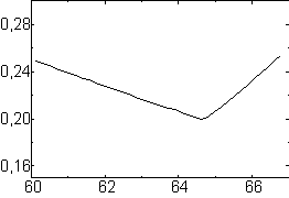
from [10] we will get the dependence of Dj
vs. the electron phase at the gap entrance (gap with length and
rf-voltage of 3 mm and 10 kV, respectively) shown in Fig.6.

One can see that in the worse case the monitor resolution
is reached of about 0.2°...0.25° of 1.3 GHz within several
degrees j0.
With installation the target near the beam current maximum the
resolution will be in 10 times less. Moreover, estimations have
shown that account of the induced charges on the target can improve
the resolution significantly. It should be noted that one of the
advantages of this technique is possibility to calibrate the monitor
using thermoelectrons from the target heated by a current (more
in detail of it in [13]).
To minimize in 50 times the longitudinal chromatic
aberration in an accelerating gap of a streak camera [7] (photocathod
- mesh distance) caused by initial electron velocity spread it
is proposed instead of a plane - parallel geometry of this unit
to use the geometry of the above mentioned one (see Fig.1.b).
It will correspond the transition from the right to left side
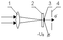
of the curves plotted in Fig.3. Figure 7 makes clear this proposal
[14].

Light is focused by an optic system (1) on a very narrow (about several mm) and thin photocathod (3) being under accelerating voltage of, for example, - 8 kV and placing from the entrance wall of the rf-resonator gap (with longitudinal modulation of the electrons and locked in phase with the beam bunches) of about 1 mm. For reaching high time resolution the transverse rf-modulation is not very convenient due to too much long of fringing rf-field and rf-field aberration. Holder (2) of the cathode (3) is taken very thin, of about 0.1 mm or less, from a free transit light materials to minimize the light dispersion effect. Temporal resolution for proposed device will be mainly defined already only by dispersion effects in windows of the camera, from linac, in Cherenkov radiator and light optics.
There is some more way for improving the time resolution. Time spread of the electrons through the accelerating gap is inverse proportional to root from an initial energy spread of the electrons, i.e. the electrons will have the same time of flight spread in the gap both for the energies from 0 to 1 eV and from 1 to 4 eV. Hence, with monochromotizing of the light at more high frequency one can increase the resolution but this way is not effective in comparison with the proposed one.
It should be noted that the known formula (see 5
in [6]) for estimation of the transit time spread in the gap is
not valid for the values about several ps and less.
There is some more advantage of this secondary electron
technique: with help the monitor one can measure a transverse
beam profile with spatial resolution of 5 nm [14]. In the case
(see Fig.1) the resonator is not switched on, instead of the multichannel
collector it is permitted to use a single channel one. High spatial
resolution is defined by the small magnitude of projection (Dz)
of the wire surface, which is visible from the collimator slit
Dx0,
on the z axis. At the angle of view of 0.1 rad. the projection
will be 1.2410-3R0, i.e. at R0
= 4 mm it
will be Dz
= 5 nm. The thickness of the region in which escaping secondary
electrons are produced is about 3 nm [11]. Composition of these
two distribution gives FWHM of about 5 nm, i.e. 200 points
per 1 mm
of a beam.
We have 6D problem to solve precisely the beam space
charge effect in the monitor. The code for this is created now,
and we expect to decrease the effect in 10...100 times using additional
specific means. In the case we will have to increase the h-distance
up to 30 mm.
Authors thank A.N.Skrinsky for the encouragement and his interest appeared to this work. A.Tron would like also to thank S.Tazzari and F.Tazzioli for their hospitality during his stay at INFN and express them his sincere gratefulness for returning him to accomplish solution of the problem dealing with the short electron bunch length measurements. Authors are grateful to V.Vaitonis for helping them in preparing the paper.
This work is supported by the Russian Fund for Fundamental
Researches under grant No.96-02-18364.
[1] R.H.Miller, R.F.Koontz, D.D.Tsang, "The SLAC Injector", IEEE Trans. Nucl. Sci., Vol. NS-12, No.3, p.804 (1965)
[2] E.Babenko et.al.,"Length Monitor for 1 mm SLC Bunches", SLAC-PUP-6203 (1993)
[3] H.Lihn et.al., "Measurement of Subpicosecond Electron Pulses", SLAC-PUB-95-6958 (1995)
[4] T.Nakazato et.al., "A Bunch Length Monitoring Using Coherent Radiation for JLC', Proc. of Int. Linac Conf., Tsukuba, p.890 (1994)
[5] Yu.N.Dnestrovski, D.D.Kostomarov, "A Study of Ultrarelativistic Chages Passing through a Circular Aperture in a Screen", Doklady Akad. Nauk, 124,4 (!959)
[6] J.C.Sheppard et.al., "Real Time Length Measurement in the SLC Linac", IEEE Trans. Nucl. Sci., Vol. NS-32, No.5, p.2006 (1985)
[7] "Guide to Streak Cameras", 1994 Hamamatsu Photonics K.K.
[8] E.K.Zavoysky, S.D.Funchenko, "Pico-femtosecond Electron-optical Chronografy", Doklady Akad.Nauk, 226, 5, p.1062 (1976)
[9] E.W.Ernst, H.VonFoerster, "Time Dispersion of Secondary Electron Emission", J.of Appl.Phys., V.26, No.6, p.871 (1955)
[10] A.M.Tron, "Secondary Electron Monitors for Ion Bunch Phase Distribution Measurements", Proc. 2nd Europ. Workshop on Beam Diagn., Travemunde, p.60 (1995)
[11] A.A.Schultz, M.A.Pomerantz, "Secondary Electron Emission Produced by Relativistic Primary Electrons", Phys.Rev., Vol.130, No.6, p.2135 (1963)
[12] I.M.Bronshtain, B.S.Friman, "Secondary Electron Emission", "Nauka", Moscow, 1969
[13] A.M.Tron et.al., "Bunch Phase Distribution Detector for the ISTRA Ion Linac Beam", this Conf.
[14] Tron's proposal