![]()
![]()
F.Brinker, A.Hagestedt, M. Wendt
Deutsches Elektronen-Synchrotron Hamburg
Notkestr. 85, 22603 Hamburg, Germany
In order to minimize the emittance dilution in next generation linear colliders precise alignment of all focussing components is needed. We report on our experiences using a pulsed wire to calibrate beam position monitors with respect to the magnetic axis of the quadrupoles used in the S-Band Linear Collider Test Facility at DESY (SBLCTF). The magnetic field along the wire and the magnetic field integral is measured by observing the transverse displacement of the wire induced by a short current pulse.
Transport of small emittance beams in next generation linear colliders demand steering of the particle beam towards the magnetic axis of the quadrupoles within a tolerance of 10 µm. For the SBLC this will be achieved with a permanent beam based alignment and a fast feedback which damps the effect of ground vibrations on the quadrupoles [5]. The procedure of the beam based alignment requires a relative precision of the BPM's of at least 4 µm and an absolute measurement of the beam trajectory with respect to the quadrupole axis within 100 µm.
In order to avoid the errors from measuring the position of the magnetic axis relative to some external reference and back to the position of the wire used to calibrate the monitor, which is inside the quadrupole, we decided to pick up the idea of Fisher et.al. [3] to use the same wire for detecting the magnetic axis. For this we use a method described by Warren [1,2] to measure the magnetic field along the wire with a strong but short current pulse. The Lorenz force acting on the wire accelerates those parts of the wire which see a magnetic field. Solving the differential equation with the initial conditions
![]() ,
, ![]()
at the position z0 behind the magnet and a time t after the current pulse of charge Q [2] gives an amplitude of:
 , with
 ![]()
where µ is the weight per unit length of the wire and c is the wave velocity which depends on the tensile force T stretching the wire. The amplitude is measured with a detector outside the magnet. Since the whole time depend of the signal can easily be measured with a digital oscilloscope this gives the magnetic field at every point of the wire as well as the field integral. If the wire is placed exactly on the magnetic axis, the signal should be zero for all times. A tilt between the wire and the magnetic axis can easily be measured.
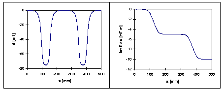
Fig. 1. magnetic field and field integral of the s-band triplet along the axis, measured with a hall probe at a distance of 4mm from the magnetic axis. Both magnets at the ends are excited to 18 T/m whereas the central region is not powered. The right graph shows which signals are expected from the pulsed wire measurement (see Fig. 5).
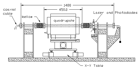
Fig. 2 Sketch of the test stand
An aluminum plate carries the magnet on movable stages and two rigid pillars to fix the wire. The wire is stretched through a stainless steel tube with the diameter of the monitor chamber to form an RF-tight coaxial system. At each side of the magnet a bellow is inserted to allow the movement of the magnet. Close to one end of the magnet the wire movement detector is placed. The distance from the detector to the end of the wire has to be longer than half of the magnet length in order to separate the original signal from the one reflected at the wire ends.
The beam position will be measured by a strip line monitor with 20 cm long electrodes. The vacuum chamber with the monitor fits closely to the magnet poles and is fixed at its position by reassembling the magnet.
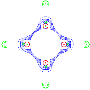
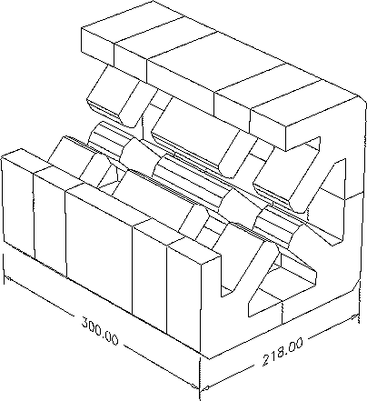
Fig. 3. left : cut of the beam position monitor for the SBLC; right : simpified view of S-Band Test Linac Triplet ( one quarter removed )
For these measurements we used the magnets of the SBLC Test Facility which are quadrupole triplets built in one yoke (Fig. 3). Focusing is done by the outer poles of 50 mm length whereas the middle part with 100 mm pole length excites the horizontally defocusing quadrupole field. The magnets have bore diameter of 35 mm and a maximum gradient of 20 T/m.
To align the magnetic axis parallel to the wire, the magnet is mounted on a table which allows the magnet to be rotated by hand around the vertical and the horizontal axes perpendicular to the wire. The magnet can be moved in the vertical and horizontal direction by stepper motors with an absolute precision of better than 5 µm. The position of the wire is not changed.
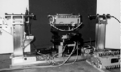
Fig. 4 View of the test stand with divided quadrupole and mounted beam position monitor
A pulse generator produces the current pulse of up to 20 A over 10 µsec by discharging a capacitor. To measure the small transverse movements of the wire we installed both a diode laser and a photodiode in each plane. The laser beam is focused in the plane of the wire to a spot size comparable to the diameter of the wire. The center of the laser spot is then adjusted to the edge of the wire. The laser intensity that reached the photodiode depends directly on the wire position and is measured by a photodiode. The DC-photocurrent is subtracted and the amplified AC-signal is measured with an digital oszilloscope triggered by the current pulse. The noise arising from ground vibrations which cause the wire to oscillate at its first harmonic (~ 60 Hz) can be reduced efficiently by averaging over typically 4-16 pulses.
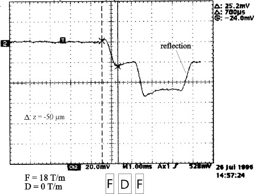
Fig. 5. typical signal of a photodiode, the distance from the wire to the magnetic axis is 50 µm in the left F-magnet and about 100 µm in the right F-magnet showing a small tilt between the magnetic axis and the wire, the middle part of the magnet ( D ) is not powered.
To align the wire with the magnetic axis we excited only the outer quadruples
of the triplet to 18 T/m while the inner part is switched off. First the
magnet is moved transversely in both planes to minimize the wire signal.
Then the magnet is rotated around its vertical and horizontal axis to get
an equal signal from both excited quadrupoles. This aligns the magnetic
axis parallel to the wire. Finally the signal is again minimized by a transverse
movement of the magnet. With this procedure, which takes about 20 minutes,
it is possible to find the magnetic axis with a precision of ![]() 20 µm.
The resolution is limited so far by movements of the wire which are induced
by ground vibrations. If necessary the resolution can be improved by shielding
the test stand against vibrations and by damping the wire oscillations.
Fig. 6 shows the result of a vertical scan with a step size of 50 µm.
20 µm.
The resolution is limited so far by movements of the wire which are induced
by ground vibrations. If necessary the resolution can be improved by shielding
the test stand against vibrations and by damping the wire oscillations.
Fig. 6 shows the result of a vertical scan with a step size of 50 µm.
The main parameters of the measurement are listed in the following table.
| wire material: | copper-beryllium |
| diameter: | 130 µm |
| weight per length: | 0.11 g/m |
| tension: | 4.5 N |
| sagitta inside the magnet | 2.7 µm |
| group velocity: | 200 m/sec |
| 1. harmonic of wire: | 66 Hz |
| charge of current pulse: | 110 µ C |
| length of current pulse | 10 µsec |
| integrated gradient of one quad: | 1 T |
| mechanical amplitude for 100 µm offset | 245 nm |
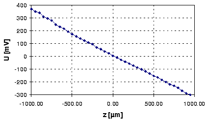
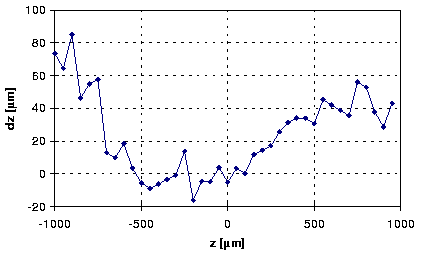
Fig. 6. measured signal from the photodiode at different distances between wire and magnetic axis (above) and the deviations of the data from a linear least squares fit
To calibrate the beam position monitor inside the triplet, the vacuum pipe is closed to build a coaxial waveguide with the wire. As soon as the wire is adjusted on the magnetic axis of the triplet it is disconnected from the high current pulse generator and connected to a network analyzer. The response to the 300 MHz signal at the four electrodes is measured while moving the magnet transversely with respect to the wire.
Close to the center, the wire position is given by
 ,
,

The data are used to fit the constants X0, Z0,
![]() X and
X and
![]() Z.
These values are unique to each monitor and will be used to correct the
readout of the monitors. Fig. 7 shows the measured data for the prototype
monitor. For large distances off axis the signals show the expected nonlinear
behavior. The precision of this measurement is about
Z.
These values are unique to each monitor and will be used to correct the
readout of the monitors. Fig. 7 shows the measured data for the prototype
monitor. For large distances off axis the signals show the expected nonlinear
behavior. The precision of this measurement is about
![]() 10 µm.
10 µm.
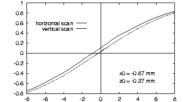
Fig. 7. measured BPM signals depending on the displacement of the wire from magnetic axis.
The detection of the magnetic axis with a pulsed wire as described here
has proven to be a reliable method to calibrate beam position monitors
with an absolute accuracy of
![]() 25 µm. Further improvements are possible
by reducing the wire oscillations due to ground vibrations.
25 µm. Further improvements are possible
by reducing the wire oscillations due to ground vibrations.
[1] R.W.Warren, "Limitations on the use of the pulsed-wire field measuring technique", NIM A272 (1988) 257-263
[2] A.Geisler, M.Ridder, T.Schmidt, "The pulsed-wire method", DELTA Int. Rep. 94-4 (1994), Univ. of Dortmund, http://prian.physik.uni-dortmund.de/pub/fel/FEL.html
[3] G.E.Fischer, J.K.Cobb, D.R.Jensen, "Finding the magnetic center of a quadrupole to high resolution", SLAC-TN-89-01 (1989)
[4] A.Hagestedt, "Prazisionsvermessung von Strahlpositions-monitoren in Quadrupol-Magneten" (1996), Diplomarbeit, FH Ostfriesland, Emden
[5] C. Montag, "An active mechanical stabilization system for LC
Quadrupoles to compensate fast ground motion", this conference