R. Assmann ![]() , C. Montag
, C. Montag ![]() , C. Salsberg
, C. Salsberg ![]()
![]() Stanford Linear Accelerator
Center, Stanford University, Stanford, CA 94309, USA
Stanford Linear Accelerator
Center, Stanford University, Stanford, CA 94309, USA
![]() DESY, 22603 Hamburg, Germany
DESY, 22603 Hamburg, Germany
Beamline stability is of great importance for future linear colliders where tolerances generally are in the micron to sub-micron range. A stretched wire system in the sealed FFTB tunnel at SLAC was used to monitor beamline motion with a sub-micron resolution. In future linear colliders low frequency changes of the beamline alignment (< 0.1 Hz) lead to untolerable quasi-statical misalignments and betatron oscillations. Since it requires time to correct those errors, it is very important to determine how often corrections are needed. We present our measurements, discuss the systematics of the stretched wire system and compare the observations with the ATL-model for ground motion.
Linear collider designs like the NLC [1] require stability tolerances in the micron or even sub-micron range. It is particularly important to show that `natural' ground vibrations and drifts do not exceed the tolerances. Fast ground motion was studied extensively in the frequency range down to about 0.1 Hz with accelerometers, geophones and seismographs [1, 2]. The frequency range below 0.1 Hz is not accessible to those measurement devices. We call magnet motions in this range `slow alignment drifts'. Slow alignment drifts of the quadrupoles limit the stability of beam linac trajectories in the time range of a few minutes to many hours. The amplitude of drifts determine how often correction algorithms must be applied and how well an emittance-optimized beam trajectory can be maintained.
In this paper we present beamline stability studies in the Final Focus Test Beam (FFTB) tunnel at SLAC. The measurements have a sub-micron resolution and were taken over 140 hours with a measurement point every 6 seconds. The data covers the time range that is of interest for the day-to-day operation of an accelerator.
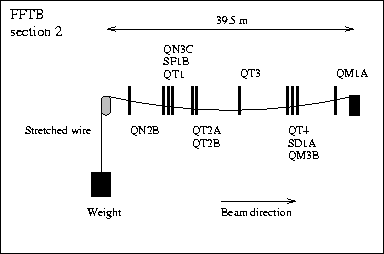
The FFTB experiment at SLAC features a sophisticated stretched wire alignment system along its beamline. The system was developed and installed by DESY as a part of the international FFTB collaboration [4]. The beamline is divided into four sections with two parallel stretched wires in each section (`left' and `right' wire). The wire lengths vary from 30 m to about 43 m in the different wire sections. An illustration of the wire in section 2 is shown in Fig. 1. An harmonic Rf-signal of 100 MHz is coupled to the wire. High resolution pick-up monitors in the quadrupoles and sextupoles are used to detect the Rf-signal with three antennas. The three signals are processed online into a horizontal and vertical `wire offset'. The expected resolution of the wire monitors is about 100 nm [5].
The original purpose of the stretched wire alignment system is to monitor and eventually adjust the absolute quadrupole and sextupole alignment in the FFTB [5]. For our study we decoupled the data aquisition from the SLC control system and improved it. Using 100 data samples for every measurement we got an alignment measurement of the whole beamline about every 6 seconds. The statistics and the time resolution of the data acquisition was enhanced by about a factor of 50. The improved time resolution allowed to study time dependent systematic effects that were inaccessible before.
The stretched wire system is easily perturbed by systematic errors. It is especially affected by temperature
variations in the FFTB tunnel. A temperature change of 1 ![]() K causes the wire sag to change by approximately
200 nm. The alignment data would show apparent alignment drifts that are indeed changes in the thermal wire
expansion. Extreme care was taken to minimize temperature variations in the tunnel. The magnets were switched on
and the FFTB tunnel was closed about one week before the start of the measurements, that were taken during the
Californian rainy season. Rain kept variations of the outside temperature small. The measurements were taken in
sections 1 and 2 in the underground part of the tunnel during a time without beam.
K causes the wire sag to change by approximately
200 nm. The alignment data would show apparent alignment drifts that are indeed changes in the thermal wire
expansion. Extreme care was taken to minimize temperature variations in the tunnel. The magnets were switched on
and the FFTB tunnel was closed about one week before the start of the measurements, that were taken during the
Californian rainy season. Rain kept variations of the outside temperature small. The measurements were taken in
sections 1 and 2 in the underground part of the tunnel during a time without beam.
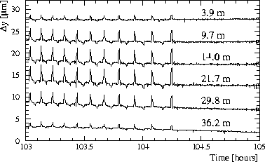
Both wires in section 2 were affected by a significant systematic
perturbation. This is illustrated in Fig. 2. Every few minutes the measured vertical wire position shows
a short variation of up to ![]() 5
5 ![]() m. The size of the effect is largest in the middle of the wire and
approaches zero at either end. It is seen for both wires but only the vertical plane. From its signature it can be
concluded that it is neither a thermal nor an electronic effect. Possible but unlikely explanations are a
periodic pull on the weight or a device that lifts up the wire every few minutes. The source of the perturbation
is not yet identified. The absolute calibration of the wire position monitors was checked by controlled
changes of the magnet offsets using magnet movers.
m. The size of the effect is largest in the middle of the wire and
approaches zero at either end. It is seen for both wires but only the vertical plane. From its signature it can be
concluded that it is neither a thermal nor an electronic effect. Possible but unlikely explanations are a
periodic pull on the weight or a device that lifts up the wire every few minutes. The source of the perturbation
is not yet identified. The absolute calibration of the wire position monitors was checked by controlled
changes of the magnet offsets using magnet movers.
Measurements with the stretched wire
system were done in March 1996. We now discuss the results. In order to remove the effects of overall wire
movements we consider the motion ![]() (or
(or ![]() ) of a magnet i in the center of the wire with
respect to the two magnets 1 and n at either of its ends:
) of a magnet i in the center of the wire with
respect to the two magnets 1 and n at either of its ends:
![]()
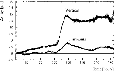
Here we assume that the magnet i is located exactly in the middle. If magnets are located very close to each other in doublets or triplets the averages of their readings are used. The analysis was done individually for the two parallel wires. It was confirmed that the results that are in good agreement. We therefore combine the data into an average. The motion of the middle magnet in section 1 is shown in Fig. 3 as a function of time for both planes. It is seen that the alignment is remarkably stable. At about 180 hours the weight was touched, explaining the sharp rise in the vertical plane. The large alignment change in the middle of the experiment (100-120 hours) corresponds to a Monday morning when the FFTB was accessed. The observed change is likely explained by this.
The ATL rule [3] states that the Rms alignment change
![]() after a time
after a time ![]() and a over a distance L is
and a over a distance L is
![]()
where A is usually specified in units of ![]() m
m ![]() /(m
/(m ![]() s). A simple approach to calculate A from our
measurements is to divide our measurement period of 140 hours into many shorter intervals, each covering a time
s). A simple approach to calculate A from our
measurements is to divide our measurement period of 140 hours into many shorter intervals, each covering a time
![]() . We then calculate the Rms alignment change
. We then calculate the Rms alignment change ![]() over those time intervals
over those time intervals
![]() . If the distance between the two end magnets is L then the observable
. If the distance between the two end magnets is L then the observable ![]() at the middle
magnet includes contributions from the two magnets each L/2 away. We can therefore use the full distance L
between the end magnets in order to calculate the constant
A.
at the middle
magnet includes contributions from the two magnets each L/2 away. We can therefore use the full distance L
between the end magnets in order to calculate the constant
A.
The results are
shown in Fig. 4 for two data sets. The upper case represents the complete set of data. We find an A of
smaller than 1 ![]() 10
10 ![]() m
m ![]() /(m
/(m ![]() s) for the horizontal data. The A from the vertical data
reaches 9
s) for the horizontal data. The A from the vertical data
reaches 9 ![]() 10
10 ![]() m
m ![]() /(m
/(m ![]() s). The calculated A grows linearly with the chosen time interval,
indicating that systematic effects are dominating the data. The ATL rule does not apply. However, from the
horizontal data we already obtain A's that are well below published results of 1
s). The calculated A grows linearly with the chosen time interval,
indicating that systematic effects are dominating the data. The ATL rule does not apply. However, from the
horizontal data we already obtain A's that are well below published results of 1 ![]() 10
10 ![]() m
m ![]() /(m
/(m ![]() s) [3].
s) [3].
It was mentioned that on Monday morning the FFTB was accessed, probably
leading to systematic instrumental drifts. If the period from 100 to 120 hours (see Fig. 3) is
excluded from the data analysis then the results in the lower part of Fig. 4 are obtained. The calculated
A's are significantly reduced for both planes and both sections. This is another hint that a common systematic
perturbation affected the data during the excluded time period. A is now almost constant for different time
intervals ![]() , as expected from the ATL rule. In addition the horizontal and vertical data sets give
similar results. The calculated A's behave largely as expected from the ATL-rule and indicate the dominance of
diffusive alignment drifts. The numerical value of A is below 5
, as expected from the ATL rule. In addition the horizontal and vertical data sets give
similar results. The calculated A's behave largely as expected from the ATL-rule and indicate the dominance of
diffusive alignment drifts. The numerical value of A is below 5 ![]() 10
10 ![]() m
m ![]() /(m
/(m ![]() s). The
horizontal data from section 2 indicates an A as low as 2
s). The
horizontal data from section 2 indicates an A as low as 2 ![]() 10
10 ![]() m
m ![]() /(m
/(m ![]() s).
s).
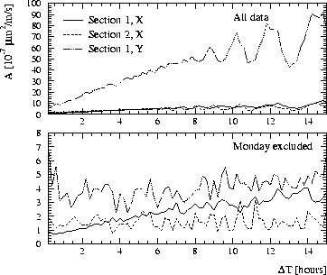
Figure 4: Calculated A constant as a function of the time interval ![]() in the ATL rule. The three different
curves refer to the horizontal (solid) and vertical (dotted) data of section 1 and the horizontal data of
section 2 (dashed). The upper results include all data. In the lower case the data between 100 and 120 hours (see Fig. 3)
was excluded. The perturbing effect of an FFTB access was such eliminated. The A
constant was determined over a distance of approximately twice 15 m.
in the ATL rule. The three different
curves refer to the horizontal (solid) and vertical (dotted) data of section 1 and the horizontal data of
section 2 (dashed). The upper results include all data. In the lower case the data between 100 and 120 hours (see Fig. 3)
was excluded. The perturbing effect of an FFTB access was such eliminated. The A
constant was determined over a distance of approximately twice 15 m.
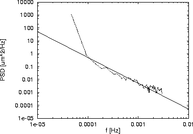
Two magnets in section 2 were studied further: QT1 and QT3. The two quadrupoles
are about 10 m apart (compare Fig. 1). The wire data was analyzed with a method that extracts the power
spectral density (PSD) of the uncorrelated magnet motion [6]. The spectrum of the uncorrelated part of
the vertical motion is shown in Fig. 5. Due to the systematic error shown before the data was filtered
digitally with a time constant of 300 seconds. The experimental power spectrum is compared with the spectrum
expected from a constant ![]() m
m ![]() /(m
/(m ![]() s).
s).
The stretched wire system of the FFTB was used to measure slow alignment drifts. Systematic instrumental effects
could largely be minimized by isolating the FFTB tunnel from environmental changes. The A constant of the
so-called ATL-rule was found to be at or below ![]() m
m ![]() /(m
/(m ![]() s) for time intervals
s) for time intervals
![]() smaller than about five hours. It was shown that 1/7 of the data is likely be affected by an
FFTB access. If this data is excluded from the data analysis we find an A of about 3
smaller than about five hours. It was shown that 1/7 of the data is likely be affected by an
FFTB access. If this data is excluded from the data analysis we find an A of about 3 ![]() m
m ![]() /(m
/(m ![]() s). A spectral analysis indicates even smaller results for A.
s). A spectral analysis indicates even smaller results for A.
The values for A that we found are below the requirements for next linear colliders like NLC. Trajectory corrections will have to be applied on an hourly time-scale. We should stress that our measurements were done in a real beamline environment including many perturbing effects. The A constant is site specific and can vary largely from site to site. However, our results clearly demonstrate that suitable sites, e.g. for NLC, can be found. Cultural noise and technical problems, like the not understood, systematic vertical wire changes in the FFTB section 2, will likely remain the major worries for the operation of future linear colliders.
We thank Dave Burke, Bob Siemann and Gus Voss for their encouragement and support. Franz Peters, Klaus Flöttmann, Reinhard Brinkmann, Jörg Roßbach, Rick Iverson, Chris Adolphsen and Robert Ruland contributed useful discussions and ideas.
Work supported by the Department of Energy, contract DE-AC03-76SF00515