Stephan T. Melnychuk, T. W. Debiak, J. Rathke, and J. Sredniawski
Northrop Grumman Advanced Technology and Development Center
1111 Stewart Avenue, Bethpage, NY 11714-3581
B. Milton, T. Kuo
TRIUMF Technologies Inc.
4004 Westbrook Mall, Vancouver, BC, Canada V6T2A3
The contraband detection system proof-of-principle device being developed at the Northrop Grumman Advanced Technology and Development Center employs a high current (10 mA) DC tandem accelerator designed to provide a beam of protons at either 1.75 or 1.89 MeV. In this paper we will describe the commissioning of the 40 keV ion injector to the tandem accelerator. The injector to the tandem consists of a filament-driven multicusp H- ion source with a virtual filter field and a triode extraction assembly, a pair of steering magnets, a solenoid lens, a pair of beam collimation slits, and a fast kicker magnet for commissioning the accelerator with a low duty-factor beam. The diagnostics in the LEBT for commissioning include a Faraday cup, a DC current toroid, isolated collimation slits, and a CW electrostatic sweep emittance scanner. We will describe the injector design, and present data on the source and LEBT operating characteristics. Results of beam phase-space measurements at the match plane of the tandem as a function of the source and LEBT parameters will be presented.
The CDS ion source, LEBT, and diagnostic station are shown in figure 1. The full system layout is discussed in more detail in ref.[1], and end to end particle simulations are presented in ref [2]. The key features of the beamline are: a filament driven volume ion source; a triode extraction system; a differentially pumped extraction region; a solenoid focusing magnet with an integrated strength of 0.0482 T m at a peak axial field of 0.3042 T and 160 A drive current; a pair of dipole steering coils; a magnetic beam kicker for fast beam shutdown and low duty factor commissioning; and a variable aperture beam collimator and beam position monitor. Beam currents are measured with a dc current toroid, and a faraday cup, and phase space measurements are made with an electrostatic sweep emittance scanner. This scanner is described in detail in refs. [3,4].
The ion source is a dc filament driven cusp H- source with a virtual filter field. The source chamber was designed and fabricated by TRIUMF and is described in detail in ref. [5].
The three grid extraction system with the relevant aperture and gap
dimensions is shown in fig. 2. This geometry was modeled with IGUN with
a 0.25 eV ion temperature, first gap voltage V1=5 kV, and a second gap
voltage V2=35kV. The beam current at the plasma boundary was chosen to
be 14 mA to allow for stripping of 20% due to e- current and 10% scraping
on the third lens electrode. The simulated rms normalized emittance was
0.093 ![]() mm mrad with a divergence of 7.75 mrad.
mm mrad with a divergence of 7.75 mrad.
The first extraction lens flange houses the electron separation magnets which form a pair of opposing dipoles. The first extraction lens flange is designed to dissipate approximately 700 W without damage to the magnets.
In the current configuration the diagnostic station is mounted at the tandem accelerator interface. When the tandem is installed the diagnostic station will be removed.
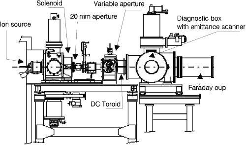
Figure 1. CDS injector and diagnostic station.
A 20 mm diameter water cooled aperture is mounted on the downstream face of the solenoid in order to shield a small diameter beam tube required for the kicker magnet. This fixed aperture and the independently variable four slit collimating aperture are the major limiting aperture in the LEBT.
Normally the source is operated at a constant arc voltage of 120 V, and the gas pressure in the source is controlled by adjusting the gas flow. At 35 A arc current typical gas flow rates range from 13 to 19 sccm.The gas flow, plasma grid bias, and first gap extraction voltage are set to maximize the H- current at each arc current. The second gap voltage has only a small effect on the H- output current and is used to control the final beam energy.
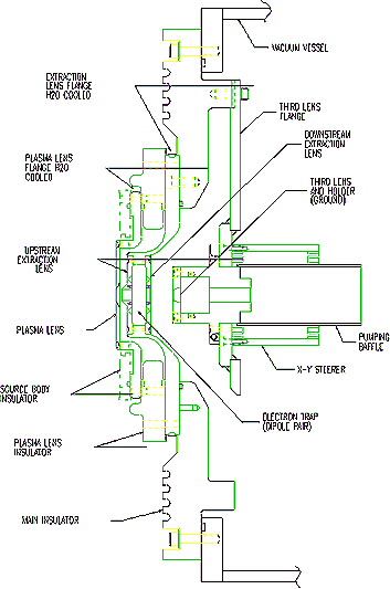
Figure 2. Extraction geometry. Plasma aperture diameter = 13 mm, first accelerating gap = 5.5 mm, extraction lens upstream aperture diameter = 9.5 mm, second accelerating gap = 19.35 mm, extraction lens upstream aperture diameter = ground electrode aperture diameter = 14.0 mm
We have measured the e- and H- output currents directly into a large diameter faraday cup located approximately 70 cm downstream from the extraction aperture with no focusing elements in the beamline and no restrictive apertures, and we measured the transported LEBT current with all of the beamline components in place as shown in fig. 1. These results are shown in fig. 3.
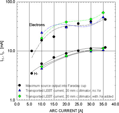
Figure 3. Ion and electron current vs. Arc current. (![]() )
Extraction directly into faraday cup. Transported LEBT current with: (
)
Extraction directly into faraday cup. Transported LEBT current with: (![]() )
residual H2; (
)
residual H2; (![]() ) Xe gas added
to LEBT. Solenoid current = 160 A. Beam energy = 40 kV.
) Xe gas added
to LEBT. Solenoid current = 160 A. Beam energy = 40 kV.
The maximum measured H- current was 11.8 mA at 36 A arc current with an electron to ion ratio of 3.6 . In the full LEBT configuration 10.9 mA, with an electron to ion ratio of 4.7, was transported with residual H2 gas only in the LEBT.
The details of the beam transport were found to be quite sensitive to the gas pressure in the transport channel. Measurement of the beam current entering a faraday cup, and the current striking an isolated beam scraper diagnostic located immediately upstream of the faraday cup showed that the faraday cup and scraper signal were oscillating 180 degrees out of phase and were synchronized with the LEBT cryopump cold head displacer motion (approximately 1 Hz). Since the sum of the scraper and faraday cup current remained constant and equal to the total beam current this shows that the beam phase space ( i. e. size and divergence) was changing. Closing the LEBT cryopump gate valve reduced the oscillation amplitude below the detection limit on the fixed scraper aperture, and addition of Xe gas into the transport channel reduced the oscillation amplitude significantly. We are in the process of setting up a measurement to correlate the phase space oscillation frequency with measured variations in the cryopump cold head temperature. We believe that the observed phenomenon is due to a variation in the degree of space charge neutralization of the transported beam due to variation in the background pressure in the transport channel. Measurement of the transported LEBT current with Xe gas added to the transport channel resulted in 11.4 mA transported.
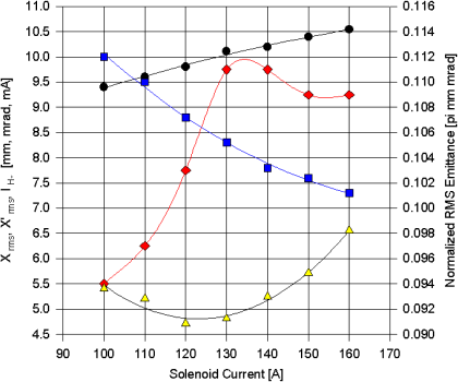
Figure 4. Beam parameters vs. Solenoid current. (![]() )
Ion current; (
)
Ion current; (![]() ) rms beam size;
(
) rms beam size;
(![]() )
rms divergence; (
)
rms divergence; (![]() ) normalized
rms emittance. Variable aperture = 40 x 40 mm2 .
) normalized
rms emittance. Variable aperture = 40 x 40 mm2 .
Figures 4 and 5 show the dependence of the transported beam current, rms size, divergence, and emittance at 40 kV beam energy, on the solenoid current and the variable collimator opening dimensions. For these measurements the emittance scanner was located 132 cm from the center of the solenoid, and the variable slit collimator center to solenoid center distance was 73.5 cm. The steering dipoles were optimized with the solenoid set to 160 A, and the variable aperture set for a 20 x 20 mm2 opening. No steering adjustments were made during solenoid or slit variation.
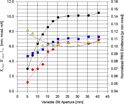
Figure 5. Beam parameters vs. Variable aperture opening.
(![]() )
Ion current; (
)
Ion current; (![]() )
rms beam size; (
)
rms beam size; (![]() )
rms divergence; (
)
rms divergence; (![]() )
normalized rms emittance. Solenoid current = 160 A.
)
normalized rms emittance. Solenoid current = 160 A.
For all the points shown in figs. 4 and 5 the beam was divergent at the scanner location. The variation in beam current with solenoid strength is due to scrape off on the 20 mm diameter fixed aperture on the downstream face of the solenoid. This is also the primary reason why the emittance drops with decreasing solenoid field.
The original CDS LEBT design was intended to produce a waist at the plane of the variable slits in order to scrape off beam halo. Experimentally we have determined that the solenoid strength is too weak to achieve this, and the beam is divergent downstream of the solenoid.
The measured beam characteristics were used in a TRACE LEBT model and matched to the expected ion source output beam with the transport channel space charge as the variable parameter. A good match was obtained for the case where the beam was fully neutralized in the region from the ion source to the downstream face of the solenoid, and 0.75 mA of space charge was turned on downstream of this point. This fitting procedure matched the measured beam phase space with the expected ion source output beam, and correctly predicted correct rms beam size measured at the variable aperture.
This is a physically reasonable picture since the location where space charge was intoduced into the beam corresponds to the location of the 20 mm fixed scraper aperture and the small diameter kicker magnet beam tube which limits the source gas flow downstream from the restrictive aperture. The space charge in the transport channel then effectively counteracts the focusing strength of the solenoid. Experiments are in progress to determine the effect of supplemental neutralizing gas injection into the LEBT while maintaining the 10-6 torr requirement at the tandem entrance region.
Phase space measurement made with the 20 mm limiting aperture removed, and a 10 cm inner diameter beam tube used in place of the existing 4.75 cm tube showed that a parallel beam could be obtained at 120 A of solenoid current. This suggests that these changes to the beamline geometry altered the gas pressure profile enough to significantly decrease the space charge current. More experiments in this area are planned.
Beam dynamics simulations using the Northrop
Grumman developed TOPKARK code show that the best match to the tandem accelerator
resulting in highest transmission is obtained at the highest solenoid setting.
The measured emittance at this value is 0.109 ![]() mm mrad.
mm mrad.
A phase space measured with the variable aperture fully open to 40 x 40 mm2 is shown in fig. 6. The ellipses drawn correspond to the best fit ellipse for a fixed intensity threshold. The outermost ellipse shown is for a 100% beam fraction.
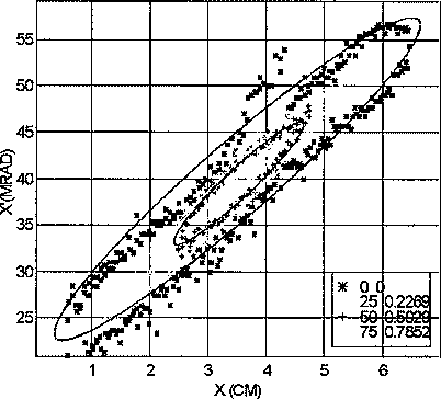
Figure 6. H- phase space at the tandem accelerator entrance
plane. I(H-) = 10.5 mA, Normalized rms emittance = 0.10 ![]() mm mrad.
mm mrad.
1. J. J. Sredniawski, T. W. Debiak, E. Kamykowski, and J. Rathke, et. al. "A Contraband Detection System Proof of Principle Device Using Electrostatic Acceleration". Submitted to this conference.
2. M. Reusch and D. Bruwiler, "End to End Particle Simulations of a 1.76 MeV Electrostatic Proton Linac for Contraband Detection. " Submitted to this conference.
3. T. W. Debiak, " A Sweep Plate Emittance Scanner for High Power CW Ion Beams", Submitted to this conference.
4. J. Rathke, M. Peacock, and J. J. Sredniawski, " Thermo-Mechanical Design of a CW Sweep Plate Emittance Scanner", Submitted to this conference.
5. T. Kuo, et. al. Rev. Sci. Instrum. 67 (1996) 1314.