The SPring-8 linac was completed and the first beam
was observed in August 1996. This Linac is used for injection
of the SPring-8 storage ring and New SUBARU ring(VUV-soft X-ray
ring, under construction) , and also used for some experiments
like the slow positron facility and the parametric X-ray source.
For the next stage, we are planning the reconstruction aimed at
the single pass FEL (SASE : Self Amplified Spontaneous Emission).
In the 1-D simulation, we get the 20 nm wavelength coherent light
with 10-20 m length undulator. The gun system will be replaced
from the thermonic HV cathode to the photocathode RF gun. And
the magnetic bunch compress section will be installed in several
areas.
The SPring-8 linac was completed and the first beam
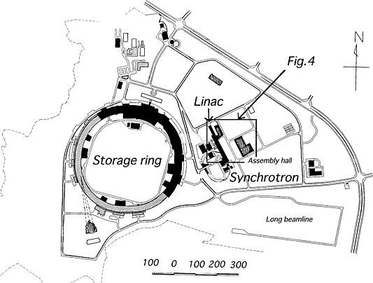
was observed in August 1996 [1]. The layout of SPring-8 site is
shown in Fig.1. And the present linac characteristic is shown
in Table 1.

Fig.1 SPring-8 site layout
Table 1: Characteristic of present linac
| Energy | 1.15 GeV |
| Normalized Emittance | 100 |
| Bunch length | 10~20 ps |
| Energy Dispersion | 1% |
| Charge | 3 nC/bunch |
| Electron Gun type | HV+, Thermal Cathode |
| Cathode | Disposed BaO (Y796) |
| Bunching | Pre Buncher + Buncher |
The linac will be operated twice a day as the injector
in the future and utilized for various applications in the rest
of the time. For example, an inverse Compton scattering for nuclear
excitation, a parametric X-ray and channeling X-ray generation,
a slow positron generation are proposed. Especially a single pass
FEL operating in the SASE mode is proposed as a VUV-soft X-ray
coherent light source that is the most important and interesting
application.
This Linac is used to injection the SPring-8 storage
ring and New SUBARU ring. And we have some plan to use some experiments
like the slow positron facility, the parametric X-ray source and
the single pass FEL. We report the study of the parametric X-ray
and the single pass FEL.
With the crystal is bombard by the electron beam,
the X-ray of the energy which satisfies the Bragg condition at
a Bragg angle is generated for the crystal plane is emitted. We
call this electromagnetic radiated emission phenomena parametrics
X-ray radiation (PXR). By choosing the crystal incidence angle
of the electron beam, it is possible to take out the X-ray of
hoping wavelength. Though the flux of coming out X-ray is also
dependent on the electron energy a little, if we use the electron
beam over 300 MeV, in the X-ray region of 14.4 keV, the conversion
efficiency is about 10-5 photon/electron.
At present, in the energy region under several hundred keV on
the average flux, it is by far abounding of the synchrotron radiation
of the storage ring. Recently, though we also examine that the
strength is made to be the several score time by the technique
with addition matching of X-ray and parametrics X-ray radiation
by resonance transition radiation (RTR). It is very low flux than
a synchrotron radiation of the storage ring yet. However, the
electron of about 1010
is contained in the 1 bunch when the linac was operated at a single
bunch. It is useful for the necessary experiment on the time resolution,
because electron beam is bunched as 10 ps. This utilization is
under preparation for the experiment, because it is corresponding
by present linear accelerator.
The high brightness high-intense electron beam is bent by the undulator, and synchrotron spontaneous radiation light which arose that time is exponentially rapidly amplified by the interaction with the electron beam, and SASE is to generate the laser beam of high brightness and narrow spectral band width. Since the optical resonator which limits the wavelength shortening of the conventional free electron laser oscillation is not used, we notice the SASE radiation source as a high luminosity high brightness small wavelength coherent radiation light source. The photon flux at the peak surpasses by far the synchrotron radiation of the SPring-8 storage ring. In addition, we have the characteristic of that it is the light in the coherent pulse and that output itself is semi-monochromatic, and the burden for the spectroscope is also little.
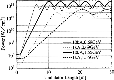
The FEL characteristics and the electron beam parameters
are shown in Table 2. And calculation result is shown in Fig.
2. At the first phase, for proof of principle, the 20 nm FEL will
be challenged. However the linac was optimized only for the injector
to the booster synchrotron, its beam characteristics are not adequate
for the FEL without improvement.

Fig. 2 Power growth in undulator
There are several key issues to realize the FEL,
for example an RF photocathode gun system, a beam transport system
and an undulator system. After these issues will be fixed, the
20 nm FEL will be realized. Then the shorter wavelength FEL, 4
nm at 1.55 GeV, will be challenged. The FEL parameter r, the power
gain length and so on are obtained by 1-D calculation [2].
| Wavelength [nm] | 20 | 4 |
| Beam energy [GeV] | 0.69 | 1.55 |
| Undulator period [cm] | 3.2 | 3.2 |
| Undulator parameter K | 1.62 | 1.62 |
| Peak current [kA] | 1-10 | 1-10 |
| Normalized Emittance [ |
1 | 1 |
| Betatron wavelength [m] | 10 | 10 |
| FEL parameter r | 2.7-5.7 | 1.6-3.4 |
| Field gain length [m] | 0.55-0.26 | 0.94-0.44 |
| Saturation length [m] | 10.4-5.2 | 16.8-8.5 |
| Undulator length [m] | 20-10 | 30-15 |
| Peak power [GW] | 1.9-40 | 2.4-52 |
| Peak brilliance [phs./sec./mm2/mrad2/0.1%B.W.] | 5.2-5.4 | 2.5-2.6 |
At first we determine the undulator parameters, the period of 3.2 cm and K=1.62, so as to minimize the field gain length. The beam energy of 0.69 GeV is realized without any improvement of the linac. However 1.55 GeV will be achieved by addition of extra accelerator tubes or energy doubler (SLED) system.
We will realize this value by means of attaching
the focusing element with the undulator. We are now developing
the 3-D calculation code which includes the element of external
quadruple field.
Some R&D studies were started already for SASE.
We introduce R&D of the electron gun for low emittance beam
and beam transport simulation.
In order to obtain a small emittance beam an RF photocathode
system is required. In the SPring-8 single cell RF photocathode
gun is developed. In case of 2cell or multicell, it is possible
to raise achievement energy in the cavity exit. However, in that
structure for suppressing the effect of adjustment mechanism and
0 modes of the resonant frequency, the coupler structure is required.
Therefore, we raise that it may become a factor of the break down
in the high field generation and that the field intensity of the
disk tip rises further than the field intensity of the cathode
surface as a defect. And, in usual accelerating cavity, by doing
the association of one combination hole, the RF power from the
waveguide supplies the cavity. However, the center of the electromagnetic-field
distribution is displaced from the central axis of the cavity,
since the electromagnetic field in the cavity is distorted by
the combination hole. Therefore, the coupler structure suppresses
the increase in the emittance by the higher mode component as
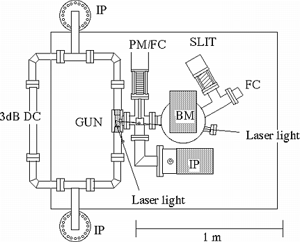
a double feed coupler structure. The layout of test stand of photocathode
RF gun is shown Fig.3.

Fig 3. Layout of test stand of photocathode
RF gun
PM : profile monitor, FC : faraday cup
From this fact, we manufacture the test equipment of the simple cavity by the double feed coupler structure, and we do the emission testing of the photocathode RF gun. It will be made to be metal cathode which is more integrated than the viewpoint of the break down prevention with the cavity in the cathode.
There are one CW seed laser and two different laser amplifier systems for photocathode. The seed laser is the Lightwave 131 whose frequency is 178.5 MHz. This frequency corresponds to 1/16 of acceleration frequency. The amplifier system is switched by retractable mirror.
The high power "Regenerative" amplifier
which generates a single pulse (bunch) will be used at the proof
of principle mode. In this case metal cathode, for example Cu
or Al, is used. The electron charge will be expected as 10 nC/bunch.
The other is 6 pass "Cascade" amplifier which generates
multiple pulse (bunch) train is used for higher average power
FEL. In this case the alkali cathode will be used, for example
Ce2Te. The electron charge will be expected as 1 nC/bunch.
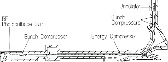
The schematic drawing of layout for SASE is shown in Fig.4. The electron beam from the RF photocathode gun, whose pulse width is expected as that of laser system 10 ps, is accelerated to 100~150 MeV. Then the beam is compressed to 1 ps. After compression the beam is accelerated to final energy.
The building for general purpose use is now under
construction. This building is located at the left side where
the linac beam can be introduced. To transport the beam the isochronous
90 degree bending system will be installed. It is easily expect
if the high current beam passes through the large despersive section
the emittance growth occurs. In order to preserve the emittance
the energy compression system is installed in front of the bending
section. After the bending section the beam is re-compressed to
the pulse width of 0.1-1 ps by means of two compressors.

Fig 4. Schematic drawing of layout for SASE
The construction of SPring-8 linac will be completed
soon. We reported some plan of the linac next stage. Various technological
development is necessary for the SASE. These are important for
the activity of the linac members.
Special thanks for supporting of SASE simulation
code to Y. Kishimoto at Naka establishment of JAERI.
[1] H. Yoshikawa, et al., "Injector Linac of SPring-8", Proc. of the 1996 Int. Linac Conf., Geneva, August 1996, to be published.
[2] K. -J. Kim and M. Xie, Nucl. Instr. and Meth. A 331 (1993) 359.
[3] T. Taniuchi, et al., "Design of RF gun for
the SPring-8 linac", Proc. of the 18th Int. Free Electron
Laser Conf., Rome, August 1996, to be published.