It is well known that coupling slots between adjacent
cells in a -mode structure reduce shunt impedance per unit length
with respect to single cell cavities. To design optimized coupling
slots, one has to answer the following question: for a given coupling
factor, what shape, dimension, position and number of slots lead
to the lowest shunt impedance drop? A numerical study using the
3D code MAFIA has been carried out. The aim was to design the
352 MHz cavities for the high intensity proton accelerator of
the TRISPAL project. The result is an unexpected set of four "petal"
slots. Such slots should lead to a quasi-negligible drop in shunt
impedance: about -1% on average, for particle velocity from 0.4
c to 0.8 c.
The TRISPAL[1] linac is designed for producing a 40 mA beam of 600 MeV protons. The aim is tritium production from spallation neutrons. The main part of the linac (from 100 to 600 MeV) is made of coupled cells cavities at 352 MHz. This rather low frequency has been chosen for klystron availability, and because SUPERFISH simulations showed that for a given beam tube diameter (= 50mm), the shunt impedance was almost the same for 352 and 704 MHz cavities. Moreover, this choice leads to a small number of cell per cavity which permits to use the simple and efficient -mode structure.
First of all, the 2D geometry has been optimized
with the code SUPERFISH [2]. The resulting cell is shown in fig.1.

In a multi-cell cavity [3], slots have to be performed between adjacent cells in order to spread the RF power within the whole cavity. They must be big enough to insure a flat -mode, but usually, this reduces the shunt impedance.
A systematic optimization of the slots has been carried out with the code MAFIA. We chose a fixed velocity value (=0.7) and started with slots inspired from the LEP cavities [4]. We computed the coupling factor, defined from the frequency difference between 0 and modes:
, (1)
and the shunt impedance drop defined from the difference
of shunt impedance between -mode and a single cell cavities:
, (2)


in which indices , 0 and 1 represent values of -mode, 0-mode and single-cell modes, respectively. As these differential values are rather small, the three cases are always computed with an identical mesh, in order to get rid of the bias due to the meshing approximation.
In order to distinguish between volume energy and
surface dissipation effects, we split the shunt impedance into
two factors; quality factor Q and geometrical impedance:
. (3)
Analogously to R, relative variations of Q and g (between -mode and single cell) are noted Q and g, respectively.
Then, we changed step by step the size, the number
and the shape of the slots. At each step, we watched how the coupling
factor and the shunt impedance drop would vary. Our goal was to
keep the same coupling factor and to minimize the shunt impedance
drop. We will not give here the winding path we followed during
the optimization process, but fig. 2 shows the starting and ending
points. Fig. 3 is a 3D view of the MAFIA computation.
We will consider here variations from the 4-petals
geometry to show that it is optimized. All the results about Q,
g or R are given with respect to a single cell cavity.
Number of slots. First of all, the number of slots per disk has been reduced to two instead of four.
Roughly, all effects are proportional to the number
of slots. The "price" for coupling is approximately
: R 0.7 .
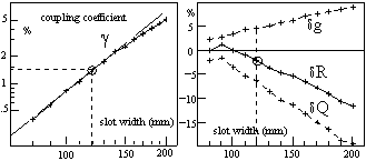
Slot width. It has been
varied from 80 to 200 mm. As shown in fig. 4, the coupling coefficient
is approximately proportional to the cube of the slot width. On
the other hand, the shunt impedance drop increases linearly from
a slot width of 100 mm. From this value, the price to pay for
increasing the coupling is: d(R)/d 3. This is much more "expensive"
than increasing the number of slots. This would suggest a slot
width of 100 mm with six slots per disk. But, compared to the
optimized solution, the shunt impedance improvement would be rather
small and the cooling circuit would be much more complicated.

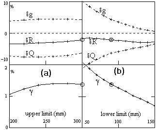
Slot height. Upper and
lower limits measured from the axis have been varied independently.
Fig. 5a shows that the lowest shunt impedance drop is reached
by the highest upper limit, while the coupling coefficient remains
constant in this area. We just kept a 5 mm margin from the highest
possible value of the upper limit (i.e. the cell radius), in a
way to simplify the mechanical design. Fig. 5b shows that the
lower limit should be as small as possible: the coupling increases
and the shunt impedance drop gets smaller. The limitation is given
by the cooling circuit.


As proton energy varies along the linac, the cell
length varies according to the velocity, and the gap length has
to be adjusted. Simulations showed that the goal frequency could
be reached by varying the gap length according to:
gap = 234 mm ( - 0.15
).
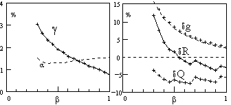
Figure 6 gives the characteristics of the coupling
slots for different speed values. According to MAFIA results,
varies approximately in 1/. The frequency detuning factor due
to the slots volume (, defined as the relative difference between
the 0-mode and a purely 2D cell) is almost constant ( 1.4%). In
all cases, the slots actually improve the geometrical impedance
(g>0), but this effect is more important for low speeds. On
the other hand, the slots always reduce the quality factor. This
effect does not seem to depend on : (Q-7%), but the result suffers
from numerical noise probably due to the mesh approximation. The
net result in shunt impedance is null for 0.6.
Influence of slots has been investigated on the first
higher order modes. We computed the bandwidth of these modes in
the "2-beans" and "4-petals" cases. As far
as we investigated monopole and dipole modes under 1 GHz, we did
not see any evidence of dangerous modes emerging. Table 1 gives
the data of the TM110 mode (generally considered as the most dangerous
one).
Table 1. TM110 mode coupling characteristics.
|
|
| |||||
The 4-petals geometry has been computed with two
other 3D electromagnetic codes: ANTIGONE [5] (which can use two
solving methods: E or H), and SOPRANO [6] . The aim is not to
compare absolute code performances, but rather to get more confidence
in the results. As a matter of fact, the codes raw results are
juxtaposed here without any consideration about meshing and solving
methods, number of points, symmetry used, computation time, etc.
Single cell results. These
may be compared with the ones of the well known 2D code SUPERFISH
(Table 2). Numerical values are very close from each other, except
for Q-value which seems underestimated by MAFIA.
Table. 2. Single-cell and 0-mode results with 3D codes (plus Superfish for single-cell)
|
|
|
|
|
|
|
Table 3. -mode results with several 3D codes
| -mode | g=R/Q | |||||
| Mafia | 351.81 | 34114 | 154.5 | 1.40 | -5.95 | +5.25 |
| Anti- E
gone H | 350.43
351.22 | 37878
33753 | 156.2
151.3 | 1.31
1.45 | -6.47
-16.9 | +3.65
+3.77 |
| Soprano | 352.01 | 38755 | 155.0 | 1.23 | -3.25 | +5.26 |
Effects of coupling slots.
According to results of table 3 (,Q,g), the slots effects are
rather coherent. The only strong difference comes from the Q drop
which is much more important according to ANTIGONE-H.
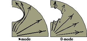
The quality factor drop may be interpreted as follows: the surface current lines, which are radial in the iris of a non coupled cell, have to deviate because of the coupling slot. This induces a current concentration on the slot edge in the -mode. In the 0-mode, the current lines do not deviate but cross through the slot to the next cell (See fig. 7) .
Until now, we have no explanation on geometrical impedance improvement due to slots. Actually, a small part of this effect (about one fifth of it) can be explained with transit time factor variation. As real cavity must be tuned anyway at the right frequency, this effect should be deduced by using the goal frequency (=2352 MHz) instead of the one of each mode in the impedance formula (eq. 3). This would lead to a conclusion a little less optimistic for g (about -1%), but as this correction should also be applied to the "2-beans" shape, the conclusion is unchanged.
A cold model experimentation is planned to settle
the point of Q-factor drop, as code results do not totally agree.

The author thanks G. Le Meur from LAL (Orsay) who
developed ANTIGONE and carried out the computations presented
here. The author is debtful to C.Riley from Vector Fields Ltd
(Oxford) for his processing with SOPRANO.
[1] M.Promé, "Conceptual studies for a high-power proton linac ", Lin. Acc. Conf. , Tsukuba, 1994, p.146.
[2] C.Bourat, "Structure CCL à 352 MHz et comparaison avec les structures à 704 MHz", Rapport Thomson DSM/DT/DIR CHB 003/95, 1995, p.2.
[3] P.Balleyguier et. al, "Study of a 433 MHz 3-cells cavity for FEL application", Europ. Part. Acc. Conf., Nice, 1990, p.910.
[4] I.Wilson and H.Henke, "The LEP main ring accelerating structure", CERN Report 89-09.
[5] G. Le Meur and F .Touze,"Priam/Antigone: a 2D/3D package for accelerator design", Eur. Part. Acc. Conf., London 1994, p.1321.
[6] D.Walsh, C.Emson and C.Riley, "Resonant cavity design using the Finite Element Method", Eur. Part. Acc. Conf., Sitges, 1996, (Proceedings to be published).