We present the experimental results on the interaction between a resistive wall and the localized space-charge waves in space-charge dominated beams. The experiments have clearly demonstrated the growth of slow waves due to the resistive-wall instability and the decay of fast waves. The spatial growth/decay rates are measured and compared with theoretical analysis.
The longitudinal instability of charged particle beams is an important issue in particle accelerators. The theoretical investigation of longitudinal velocity instability began long time ago in connection with the development of microwave tubes [1-2]. The amplification of longitudinal density fluctuations was first observed in an electron stream surrounded by a resistive wall by Birdsall et al. [3]. The first theoretical work on the longitudinal resistive instability for intense coasting beams in particle accelerators was performed by Neil and Sessler [4]. Following these early studies, considerable theoretical work has been done mainly for circular high-energy particle accelerators [5].
In recent years, the problem of longitudinal instabilities has received new attention in connection with induction linear accelerators as drivers for heavy ion inertial fusion. When the heavy ions are accelerated by induction gaps, the beam sees dissipative impedances. The interaction between the intense beam and the gap impedances causes the longitudinal instability which may be detrimental to the beam. Though there have been extensive theoretical and computational investigations on the instability [6-11], an experimental study of the instability with heavy ion machines would be too difficult and too costly since a large-scale facility would be required. This is evidenced by the conventional spatial growth rate formula
, (1)
where Rw* is the wall resistance per unit length, L0 is the beam line-charge density, q/m is the ratio of charge to mass of the particles, g is the relativistic Lorentz factor, e0 is the permittivity of free space, and g is a geometry factor of the order of unity. With heavy ions in induction linear accelerators an e-fold growth rate would require a machine of hundreds of meters in length, according to Eq. (1).
We have designed an experiment to study the longitudinal instability with space-charge dominated electron beams [12]. By taking advantage of the small mass m of electrons, the large line-charge density L0 in space-charge dominated beams, and using a rather large wall resistance Rw*, we are able to measure the instability growth rate in a small-scale facility. A novel feature in our experiments is the fact that we employ localized space-charge waves. Conventionally, the longitudinal instability has been studied with sinusoidal waves. This approach does not usually lead to a complete solution of the problem. In practice, perturbations to beams in accelerators are often in the form of localized short pulses. Thus, a time-domain approach based on localized perturbations in the experiment provides a better picture and a more realistic and complete analysis of the instability.
The experimental setup, as shown in Fig. 1, consists
of a short-pulse electron beam injector, a resistive-wall channel,
and diagnostics. The injector contains a gridded electron gun,
which can produce desired beam parameters with localized perturbations.
The key component of the resistive-wall channel is a glass tube
of about 1 m in length and 3.81 cm in inner diameter. The inner
surface of the glass tube is coated with Indium-Tin-Oxide. The
total resistances of two tubes employed in the experiments are
5.44 kW
and 10.1 kW,
respectively. The beam is focused by a 1.4-m long uniform solenoid.
The diagnostics includes two fast wall-current monitors at the
entrance and the exit of the resistive tube to measure beam current
signals with perturbations. Typical beam parameters are 3-8 keV
in energy, 25-140 mA in current, and about 100 ns in duration.

In the experiment, electron beams with localized perturbations are generated in the gridded electron gun and transported through the resistive-wall channel. By employing the technique described in a previous paper [13], single slow or fast waves can be developed on these beam pulses. The interaction between the space-charge waves and the resistive wall leads to the instability. Figure 2 shows the growth of a single slow wave where (a) depicts the beam current signals with a slow wave at the entrance and exit of the channel, (b) is the zoom-in view of the slow wave before and after the resistive channel. It is clear that the amplitude of the slow wave is increased as expected. A similar picture is obtained for the decay of a localized fast wave after passing through the resistive-wall channel.


For localized perturbations, the spectrum of space-charge waves covers a wide frequency range. In general, the spatial growth/decay rate ki of the longitudinal instability under the long-wavelength limit is given by [14]
. (2)
Here K is the generalized perveance, Z0=1/(e0c)=377 W, w is the perturbation frequency, and Xs* is the space-charge wave impedance per unit length given by
. (3)
It is obvious that both the growth rate and the space-charge wave impedance are frequency-dependent. If the space-charge wave impedance dominates over the wall resistance, the spatial growth rate formula, Eq. (2), reduces to Eq. (1).
In the experiments various perturbation waveforms from a Gaussian-like or triangular shape to a "trapezoidal" one with a flat top have been employed for the instability study. The trapezoidal-like perturbation waveform contains a wide frequency spectrum. The long-wavelength limit condition is still satisfied for most frequency components of this spectrum in the experiments, so that Eq. (2) does apply. For the low frequency components, the space-charge wave impedance is comparable to or even smaller than the wall resistances. Hence Eq. (1) is not valid any more. The growth/decay rate for these frequency components would be smaller than that determined by Eq. (1). Overall, the amplitude increase/decrease of localized slow/fast waves are smaller than what is usually expected according to Eq. (1).
In the analysis, we first find the frequency spectrum density of the measured input perturbation signal hi(t) at the entrance of the resistive channel by the Fourier transformation
. (4)
The calculated output signal ho(t) at the exit of the channel is obtained by the inverse Fourier transformation
, (5)
where L is the length of the resistive tubes, and kr(w) is the perturbed wave number given by
. (6)
The function ho(t) is compared with the measured output signal.
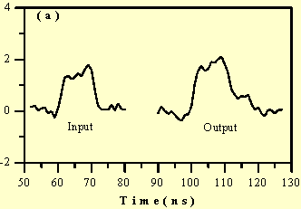
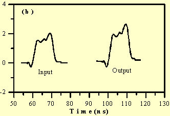
In Fig. 3 we compare the experimental data for a
slow wave of the trapezoidal-like perturbation with the analysis.
Here (a) depicts the experimental perturbation at the entrance
(input) and the exit (output) of the channel. In Fig. 3(b) the
"input" denotes the digitized input signal in (a), while
the "output" represents the slow space-charge wave at
the exit of the channel, calculated from Eqs. (4)-(6). A similar
comparison between the experiment and analysis for a fast wave
can also be made. In both cases (slow and fast waves), there is
good agreement between the experiment and the analysis in terms
of the average wave amplitude. The rather significant difference
on the edges of the perturbation waveform is due to the effect
of high frequency components beyond the long wavelength limit
in the perturbation signal, the effect of distributive capacitance
along the resistive wall, and some reflections in the measured
signal from mismatch. These are a subject of future study.


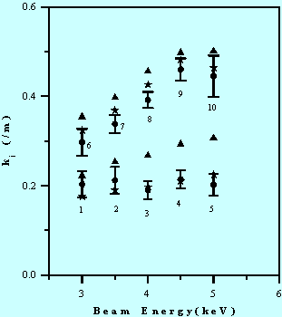
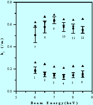
Figure 4 shows the amplitude growth rates of the slow waves with the trapezoidal waveforms for different beam parameters and wall resistances, where the dots with error bars represent the experimental results, the stars are from the Fourier analysis, and the triangles are from Eq. (1). The data points 1-5 are from the 5.44 kW tube, while the data points 6-10 are from the 10.1 kW tube. Note that for each data point at a certain beam energy, the beam current as well as the geometry factor g, differ. A similar plot for the decay of fast waves with the same perturbation waveforms is shown in Fig. 5. These figures show that the amplitude changes of localized space-charge waves passing through a resistive channel are smaller than the theoretical values calculated from Eq. (1).


The resistive-wall instability experiment has demonstrated the growth of slow waves and the decay of fast waves. The theoretical analysis of the evolution of the pulse shape in the resistive channel based on Fourier transforms shows good agreement with the measurement except for edge effects where the distributive capacitance plays a role and the long wavelength assumption breaks down. We have found that the amplitude change of localized space-charge waves due to the instability is smaller than that calculated from the conventional growth rate formula of Eq. (1).
This research is supported by the US Department of Energy.
[1] W. C. Hahn, Gen. Electr. Rev. 42, 258 (1939).
[2] S. Ramo, Phys. Rev. 56, 276 (1939).
[3] C. K. Birdsall, G. R. Brewer, and A. V. Haeff, Proc. IRE 41, 865 (1953).
[4] V. K. Neil and A. M. Sessler, Rev. Sci. Instr. 36(4), 429 (1965).
[5] M. Reiser, Theory and Design of Charged Particle Beams, (John Wiley & Sons, Inc., New York, 1994), Section 6.3.
[6] S. Humphries, Jr., J. Appl. Phys. 51, 2338 (1980).
[7] E. Lee, in Proc. of the 1981 Lin. Accel. Conf., Santa Fe, NM, 1981, edited by R. A. Jameson and L. S. Taylor, p.263.
[8] J. Bisognano, I. Haber, L. Smith, and A. Sternlieb, IEEE Trans. Nucl. Sci. NS-28, 2513 (1981)
[9] P. J. Channell, A. M. Sessler, and J. S. Wurtele, Appl. Phys. Lett. 39(4), 359 (1981).
[10] I. Hofmann, Z. Naturforsch, 37a, 939 (1982).
[11] D. A. Callahan, A. B. Langdon, A. Friedman, and I. Haber, in the Proc. of the 1993 Part. Accel. Conf., Vol. 1, p. 730, Washington, D. C., May 17-20, 1993.
[12] J. G. Wang, M. Reiser, W. M. Guo, and D. X. Wang, Particle Accelerators, Vols. 37-38, 181 (1992).
[13] J. G. Wang, D. X. Wang, and M. Reiser, Phys. Rev. Lett., 71(12), 1836 (1993).
[14] J. G. Wang and M. Reiser, Phys. Fluids B 7 (7), 2286 (1993).