A prototype rf power source based on the Relativistic
Klystron Two-Beam Accelerator (RK-TBA) concept is being constructed
at the Lawrence Berkeley National Laboratory to study physics,
engineering, and costing issues. The prototype, called the RTA,
is described and compared to a full scale design appropriate for
driving the Next Linear Collider (NLC). Specific details of the
induction core test and pulsed power system are presented. Details
of the 1-MeV, 1.2-kA induction gun currently under construction
are described.
For several years a Lawrence Berkeley National Laboratory
(LBNL) and Lawrence Livermore National Laboratory (LLNL) collaboration
has studied rf power sources based on the RK-TBA concept [1].
This effort has included both experiments [2] and theoretical
studies. A preliminary design study for a rf power source using
the RK-TBA concept suitable for an rf power source upgrade of
the NLC collider design (TBNLC) has been published [3]. The design
specifically addressed issues related to cost, efficiency, and
technical issues. For a 1.5-TeV center-of-mass energy design,
the rf power source is comprised of 76 subunits, each about 340
m in length with 150 extraction structures generating 360 MW per
structure. Estimated conversion efficiency of wall plug energy
to rf energy for this source could be greater than 40%. Theory
and simulations showed acceptable drive beam stability through
the relativistic klystron, and no insurmountable technological
issues were uncovered.
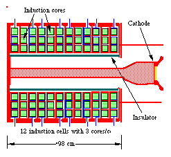
We have established the RTA test facility [4] at LBNL to verify
the analysis used in the design study. The principle effort is
constructing a rf power source prototype where all major components
of the TBNLC rf power source will be tested. The different sections
of the RTA are described in Table 1. Due to fiscal constraints,
the RTA will have only 8 rf extraction structures. Table 2 is
a comparison between the pertinent parameters for TBNLC and the
RTA. The pulsed power system and induction cells in the extraction
section will be similar for both machines, allowing a demonstration
of the wall-plug power to drive beam power conversion efficiency
and establishing a basis for costing of the components.
Table 1
RTA Accelerator Sections
|
|
| |||
| Electron gun | |||||
| Accelerator | |||||
| Chopper | |||||
| Adiabatic compressor | |||||
| Extraction section | |||||
| Diagnostic section |
† Beam parameters at the end of the section.
Table 2
Comparison between RTA and the TBNLC.
| Parameter | ||
| Pulse duration
Flat-top Rise time |
|
|
| Current
Pre-chopper Extr. section (dc) Extr. section (rf) |
|
|
| Beam energy
Injector Chopper Extraction |
|
|
| Bunch compression | ||
| Beam transport in
extraction section Betatron period Lattice period Phase advance Occupancy Pole tip field Beam diameter |
|
|
| RF Power
Frequency Power/structure Structure type Output spacing |
|
|
Conversion of wall plug power into induction drive
beam power is a significant factor in the rf power source efficiency.
The efficiency of a TBA induction accelerator depends on several
factors. Beam transport dynamics will determine the size of the
beam pipe. The rf power requirement determines the pulse duration,
beam current, accelerating gradient, and repetition rate. Once
these factors are established, the outer radius and material of
the core can be calculated from: DVDt
= DBAFp,
where DV
is cell voltage swing, Dt
is pulse duration, DB
is core flux swing, A is core cross section, and Fp
is core material packing factor. The core volume increases nearly
as the radius squared, so smaller, more efficient and lower cost
induction cells can normally be obtained by using higher DB
materials and minimizing the inner radius.
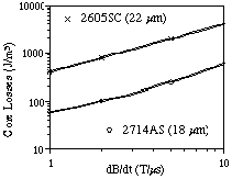
Several core materials have been tested at the RTA Test Facility [5]. Two METGLAS® alloys, 2605SC and 2714AS, have been selected for use in the RTA. The alloy 2605SC has a DB of ~ 2.5 T with a core loss of ~ 2 kJ/m3 for a 400 ns pulse and 22 µm thick ribbon. The alloy 2714AS has a lower DB, ~ 1.1 T, but a much lower core loss of ~ 150 J/m3 with 18 µm ribbon. The core tests are performed with the expected pulse shape and duration for accurate loss measurements. For our TBNLC geometry, the low core loss 2714AS can achieve a conversion efficiency of wall plug power to drive beam power of 59%, a substantial improvement over 2605SC.
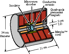
The modest repetition rate (120 Hz) and current rise time (100 ns) envisioned for the NLC permit the use of a simple, and cost effective thyratron driven modulator. The total induction cell core is segmented longitudinally into smaller cores each individually driven at 20 kV or less. Driving at this voltage level avoids a separate step-up transformer and allows for switching with fast inexpensive single-gap tubes. Length of the induction cell, thus number of cores per cell, is set by geometrical constraints due to extraction structures, magnet positions, etc. The TBNLC design in Fig. 1 has five cores per cell while the RTA has three cores.
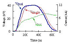
Beam energy flatness is an important issue affecting beam transport and rf phase variation. The current required to drive the cores is nonlinear for a constant amplitude voltage pulse since the inductance of the core decreases as saturation of the material is approached. The effect is more pronounced for high aspect ratio (r/z) cores due to non-uniform saturation starting at the inner radius propagating outward. This effect is shown in Fig. 3 where the voltage pulse has ~200 ns of flat top during which the drive current increases non-linearly. The generated voltage amplitude can be kept constant, within bounds, as the material approaches saturation by tapering the impedance of the PFN stages. Our PFN will consist of many coupled L-C stages.
We have been testing pulsed power prototypes using
a 3-core injector cells. In the prototype we have used EEV CX1538
and TRITON F-232 thyratron tubes. The injector cell design calls
for 14 kV/core or 40 kV/cell. Early test performed using a CX1538
tube yielded a rise time (10% to 90%) of about 150 ns with a voltage
flat top of 120 ns (see the Vsingle
trace in Fig. 3), however a pretrigger applied to an additional
grid on the tube gave performance close to the design (100 ns
rise time, 200 ns flat-top). With the pretrigger to an additional
grid on the tube we were able to get the rise time to down to
100 ns and obtain a voltage flat top of 180 ns (shown in the Vdual
trace in Fig. 3). The Idual
trace in Fig. 3 shows the drive current for the cell with a 40
simulated beam load. The F-232 tube has lower internal inductance
as well as a higher di/dt rating. It also gave performance close
to the design criteria.
The injector consists of two sections, a 1-MV, 1.2-kA induction electron source, referred to as the gun, followed by several induction accelerator cells to boost the energy to 2.8 MeV. Two goals of the design are minimizing electrical field stresses in the gun and realizing the lowest possible emittance growth. Gun induction cores are segmented radially to reduce the individual aspect ratios with each driven separately at about 14 kV. Components of the induction cells for the gun are in fabrication.
A novel feature of the gun design is the insulator, a single, 30 cm ID, PYREX® tube with no intermediate electrodes. Average gradient along the insulator at the operating voltage of 500 kV is ~ 5.1 kV/cm. Maximum fields at the triple points, intersection of insulator, vacuum, and metal, are less than 3.5 kV/cm. Maximum surface fields in the cathode half of the gun are about 85 kV/cm. Our design allows for the addition of intermediate electrodes and/or substitution of a ceramic insulator to offset the increased risk associated with this approach.
The focusing solenoidal field profile must be optimized for the injector to control the beam radius while minimizing emittance growth. A new electrode package and larger dispenser cathode will likely be required for the desired low emittance 1.2-kA, 1-MeV electron beam. The design goal is for beam radius less than 5 mm and horizontal normalized edge emittance less than 250 '-mm-mrad at the end of the injector. Alignment of the solenoids is critical to avoid corkscrew motion and emittance growth. Incorporating homogenizer rings [6] with the solenoids could reduce the need for correction coils and simplify alignment.
Experience operating other induction accelerators
has shown that careful alignment of the solenoids may not be sufficient
to reduce the amplitude of the corkscrew motion [7] to the 0.5 mm
desired for the RTA injector. We plan to use a time independent
steering algorithm developed at LLNL to control steering coils
on the solenoids. The algorithm corrects for the Fourier component
at the cyclotron wavelength of the field error.
Beam dynamics issues related to longitudinal and transverse stability, modulation, and transport have been presented in detail elsewhere [3, 8]. A brief description of these issues is given here. Initial beam modulation is accomplished with a transverse chopping technique. After this modulator section, an adiabatic compressor, a system of idler cavities and induction accelerator modules, is used to bunch the beam and further accelerate it to an average energy of 4 MeV. The lower frequency component of the transverse beam breakup instability is controlled by Landau damping. Control of the higher frequency component, excited in the rf cavities, is accomplished with the focusing system in a technique that we refer to as the "Betatron Node" scheme. The rf extraction structures are appropriately detuned to compensate for space charge and energy spread effects so that the longitudinal current distribution is stable.
After the adiabatic compressor, the beam enters the
extraction section, where beam energy is periodically converted
into rf energy (via extraction cavities) and restored to its initial
value (via induction modules). Both traveling wave (TW) and standing
wave (SW) structures are being considered for the extraction section
of the RTA. The TBNLC design [9] uses TW structures to reduce
the surface fields associated with generating 360 MW per structure.
RTA is designed to generate 180 MW per structure. Thus, inductively
detuned SW cavities are a practical alternative.
[1] Sessler, A.M. and Yu, S.S., Phys. Rev. Lett. 54, 889 (1987).
[2] Westenskow, G.A., and Houck, T.L., IEEE Trans. on Plasma Sci., 22, 750 (1994).
[3] "An RF Power Source Upgrade to the NLC Based on the Relativistic-Klystron Two-Beam-Accelerator Con-cept," Appendix A of the Zeroth-Order Design Report for the Next Linear Collider, SLAC Report 474, Stanford Unversity, Stanford, CA, May 1996.
[4] Houck, T.L., and Westenskow, G.A., "Prototype Microwave Source for a Relativistic Klystron Two-Beam Accelerator" to be published in IEEE Trans. on Plasma Sci., Special Issue on High Power Microwave Generators.
[5] Reginato, L., et al., "Engineering Conceptual Design of the Relativistic Klystron Two-Beam Accelerator Based Power Source for 1-TeV NLC," Proc. 1995 IEEE Particle Accelerator Conf., p. 743.
[6] Feinberg, B., et al., Nucl. Instr. and Meth., 203, pp. 81-85 (1982).
[7] Allen, S.L., et al., "Measurements of Reduced Corkscrew Motion on the ETA-II Linear Induction Accelerator," Proc. 1991 IEEE Particle Accelerator Conf., pp. 3094-3096.
[8] Houck T.L., et al., "RK-TBA Prototype RF Source," Proc. 1996 Pulsed RF Sources for Linear Colliders Workshop.
[9] Kim, J.S., et al., "RF Structure Design for the TBNLC," to be published in the 1996 Linac Conference proceedings.