An upgrade for the front section of the Nuclotron
Injector is presented. The aim of this upgrade is to decrease
the minimal charge-to-mass ratio of ions accelerated from 0.33
to 0.28. It consists of a transverse wall placed 1.1 m from the
front flange of the linac, separating the 14.4 meter tank into
two distinct RF cavities, and replacement of the 11 drift tubes
in the first cavity, extending the transverse acceptance of the
linac. This upgrade makes possible the acceleration of iron, cobalt,
copper and krypton ions in the Nuclotron. Upgrades to both Laser
and EBIS sources are also planned, to increase the linac output
current and the atomic number of accelerated ions.

The mass limit for the LU-20 Nuclotron Injector is currently set by the requirement that ion charge-to-mass ratio Z/A must be equal to or greater than 1/3.An upgrade of the linac front section has been proposed, and has now in fact been carried out, allowing for acceleration of ions with Z/A=0.28. This paper describes the upgrade; commissioning experiences are detailed in a follow-on paper.
The LU-20 linac was originally constructed as a proton injector. For ion acceleration, operating in the second harmonic mode is necessary, leading to unfavorable transit-time factors for the original drift-tube geometries. Electric fields needed for efficient acceleration are shown in Fig. 1, requiring either a very large tank tilt, or a general increase of field levels.
As producing the required field distribution is not
possible with the present RF system, operation in the 2bl
mode to date has been achieved by increasing the overall strength
of the accelerating field to a level where capture of particles
can take place. This choice is not optimum: in addition to not
being able to reach the most desirable gradients for the front
end of the tank, the extra RF power is wasted on the largest part
of the linac tank. Moreover, the existing quadrupole lenses in
the front end of the linac are unable to supply the gradients
required to effectively focus ions with Z/A<0.5, leading to
further beam losses throughout the linac. By placing a diaphragm
at the location of the 11th drift tube, the tank is divided into
two separate resonators that can be excited to different levels.
By replacing the first 11 drift tubes, as well, and improving
the quadrupole magnets in them, better accelerating and focusing
efficiency can be achieved. Note, no changes are required to the
remainder of the linac.
To provide the greatest energy gain of a particle,
the gap factor = g/L (g is the gap between drift-tube
faces and L is the length of the accelerating cell) should
be as small as possible and constant. The tuning of each accelerating
cell to the resonant frequency is realized by selecting the drift
tube diameter.

Operational experience for linacs in our frequency range (145 Mhz) indicates that stable operation is possible if electric field gradients do not exceed 11MV/m on the axis of the accelerating gaps (Eg) and 25MV/m on the surfaces of the drift tubes (Es) [1]. From these considerations, we have selected a gap factor of 0.2 and have set the rounding radii of the drift tubes at Rt=12mm and rt=8mm (see Fig. 2). To characterize the accelerating structure, it is necessary to know the dependence of the transit-time factor T (at the harmonic number k) on the velocity of an accelerating particle. As a first approach, for the simplified model of the accelerating period (Rt=0 and rt=0) the dependence of the diameters of the drift tube on particle velocity was determined by the method of partial areas [2]. Then using the results of these calculations and the chosen geometric parameters 2a, Rt, rt and , a full-scale model of an accelerating period was made (see Fig. 2). It has a movable bottom and changeable drift semitubes, and so can be configured to make measurements for any of the relevant accelerating periods.
The calculation of the accelerating structure was
carried out by the method of sequential approaches using experimental
dependences of T(), d() [3]:
The new drift tubes differ in construction from the old ones by the omission of tuning disks. The new drift tubes are also not vacuum-tight. The drift tubes are fastened using two rods; the principal one is used to feed and cool the quadrupole lenses, the second one located under 90 prevents mechanical vibration of the drift tubes. The ends of the rods are fixed in special adjusting devices for precise alignment.
A special tuning unit (cylindrical piston) is installed
at the input wall of the first tank section to provide exact tuning
to the resonant frequency of the main compartment. The frequency
range allowed by this tuner is 100 kHz, two times wider than expected
detuning.
A FODO focusing periodicity was selected for the
new drift tubes, to match that in the main tank.

To obtain acceptable values of the gradients in the
quadrupole lenses and not to decrease significantly the throughput
of the linac, a compromise value of cos equal to 0.6 was
taken, where is the average phase advance. For ions with Z/A=0.3,
the maximum gradients reach values up to 100 T/m. Fortunately,
because of the very low duty factor required for the LU-20, these
magnets can be run in a pulsed mode. A Brookhaven concept [4]
with a trapezoidal pole configuration has been adopted for the
magnet design, based on simplicity of manufacturing and assembly,
and on a pole profile which provides good field gradient with
acceptable nonlinearities. A schematic of this design is shown
in Fig. 3. The full aperture of the quadrupole lens is set at
2rm=2.2 cm, the size of the flat pole is chosen according
to the recommendations of Plotnikov [5], to suppress the sextupole
component of the magnetic field. The magnet cores are assembled
from sheet electrotechnical steel, and consist of two halves joined
by a metal ring.

This construction allows a greater number of turns
in the winding and hence greater field gradient, and also simplifies
assembly of the quadrupole magnets.

Each quadrupole magnet is an integral part of its
drift tube, so the magnetic axis of the lens is rigidly connected
to the aperture of the drift tube. The misalignment of the linac
geometric axis to the lens magnet axis does not exceed 0.05mm.
The lens median planes are adjusted using a special fixture to
an accuracy of 30. After assembly, the magnetic characteristics
of the new drift tubes were measured on a test stand. The dependence
of the gradient on the exciting current in lens number 3 is shown
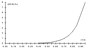
in Fig. 4. The dependence of the magnet field nonlinearity on
radius at the working current in the exciting winding is shown
in Fig. 5.
Table 1
The main parameters of the accelerating-focusing
structure of the new first tank are shown in Table 1.
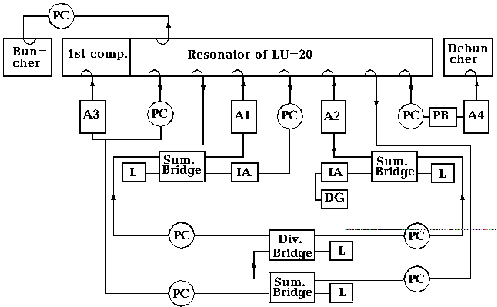
A block-diagram of the RF-power system is shown in
Fig. 6.This system provides maximum excitation in the linac tanks.
The main resonator tank is powered by two "Rodonit"
autogenerators, each with an output power of 3MW. Both generators
have a positive feedback loop through the tank. To excite the
main mode TM010 the highest modes TM011
and TM012 are suppressed.

PC are Phase Changers, A1, A2 are amplifiers (1st
and 2nd channels of "Rodonit", IA are intermediate amplifiers,
L are 75 Ohm loads, PB is a phase bridge, A3 is the generator
of the 1st tank, A4 is the debuncher generator, DG
is the reference source.
Table 2. The main parameters of the RF-amplifier
| Number of cascades | 3 |
| RF-power in pulse | 0.5MW |
| RF-pulse duration | 500s |
| Minimum pulse to pulse duration | 2000 |
| Working frequency | 145.00.5MHz |
To feed the first tank a standalone generator (A3, Fig. 6) was built. This generator is excited from the main resonator via a connecting loop. The anode circuits of the generators are fed by a modulator consisting of a double pulse-forming pulse-line. The main parameters of the RF-amplifier are shown in Table 2.
Automatic control systems provide the required amplitude
and phase stability. This system should provide adequate compensation
for phase perturbations arising in the resonators and RF-amplifier
cascades. As there are two standalone objects, each requiring
phase perturbation compensation, two automatic control systems
are needed. One of them is an automatic phase tuning system (APT),
the second system is an automatic frequency tuning system (AFT).
Completion of the Nuclotron Injector Upgrade project
will require, in addition to the linac modifications, improvements
to the ion sources to provide higher ion intensities and better
charge-state distributions. These improvements have been studied
and designed, but have not been implemented in the present phase
of the upgrade project.
An upgrade of the laser ion source, currently used
for beams up to Mg, has been planned as a part of this Upgrade
project [6]. A new CO2 laser will be able to operate
at a frequency up to 5 Hz at an output pulse peak power up to
25 MW and a beam divergence of less than 510-4 rad.
The planned laser beam focusing system with a parabolic mirror
will provide a flux density up to 31011 W/cm2
on the target. The up-dated laser ion source is expected to produce
Fe16+ ion beams at an intensity of more than 1010
ion/pulse.
The "Krion-2" EBIS source [7] will also
be upgraded. A new electron optics system will provide an 8 keV,
2.5 A electron beam with about 200 A/cm2 beam density.
To reach these electron beam parameters with a magnetically immersed
Pierce type gun, a 5 T superconducting solenoid will be manufactured
using a high precision winding technology. Design of the electron
collector and the ion beam optics, based on IGUN [8] simulations,
has been performed. The electron collector design provides satisfactory
formation of about 1 mA of ion beam with 1.5 keV electron beam
energy on the collector surface. The upgraded "Krion-2"
EBIS will provide a variety of ion species with high and moderate
charge states. For example, iron ion beams of Fe16+
and Fe24+ will have intensities of 3109
ion/pulse and 1109 ion/pulse respectively. Note, to
inject solid materials into the EBIS trap, an external MEVVA-type
ion source will be used [9].
[1] Murin B.P. et al., "Linear Accelerators ", v.2, Moscow, Atomizdat (1978).
[2] Hahu W.C. "Applied Physics" 1941, v12, N1, p.62-66
[3] Murin B.P. et al., "Linear Accelerators ", v.2, Moscow, Atomizdat, (1978).
[4] Damm R. et al. Proc. of the 1970 Proton Linear Accelerator Conf., v1, USA, Batavia, NAL, p561-577 (1970).
[5] Plotnikov V.K. PTE, NN 2, 29 (1962).
[6] A.I. Govorov , I.V. Kalagin, V.A. Monchinsky at al., Proc. of the 1994 Int. Linac Conf., Tsukuba, Japan, V1, p.372 (1994).
[7] E.D.Donets, in "Physics and Technology of Ion Sources", Ed.by I.G.Brown; John Wiley and Sons, p.245 (1989).
[8] R.Becker, private communication (1988); Rev.Sci.Instr. 63, (1992), p.2756; Rev.Sci.Instr. 67, p.1132 (1996).
[10] I.G.Brown, S.Anders, M.R.Dickinson, P.B.Fojas,
R.A.MacGill, Rev.Sci.Instr. 65, (4), p.1260 (1994).
* This work was partially funded by the US Department
of Energy, Industrial Partnering Program (Offices of Nuclear Nonproliferation)
in partnership with the Lawrence Berkeley National Laboratory.