The original UNILAC injector uses PENNING type ion sources and charge states up to 10+ for uranium beams. The beam intensities for very heavy ion species out of that injector are too low by almost a factor 300 to fill the Heavy Ion Synchrotron SIS up to its space charge limit. At present only ion sources like CHORDIS ( 1+ and 2+ charged ions) or MEVVA, which generates charge states up to 4+ above mass 180 can provide the requested beam intensities during a pulse duration of 100 µs.
The IH-DTL with its high acceleration efficiency offers the possibility to replace the 34 MV prestripper linac by a new 91 MV linac while keeping the positions of the pre-injectors and of the gas stripper untouched. The actual prestripper frequency of 27 MHz will be replaced by 36 MHz, being one third of the poststripper linac frequency.
The beam dynamics of 'Combined Zero Degree Synchronous Particle Sections' is applied on the two IH cavities.They generate averaged effective voltage gains of 4.3 MV/m.
The paper describes
the new linac, especially focusing on the rf structures and on
the beam dynamics along the IH-DTL.
The rebuilt of the 1.4 MeV/u UNILAC prestripper linac is part of a program to extend the UNILAC capabilities [1]. Besides the traditional 25 % duty factor low intensity operation short high intensity beam pulses have to be delivered to the synchrotron SIS which is in operation since 1990. It can be filled up to its space charge limit only for ion masses below 40 at present [2]. One reason is the drastic reduction of very-heavy ion beam intensities down to around 2% by stripping processes at 1.4 MeV/u and at 11 MeV/u used for standard SIS injection.
20Ne beams from CHORDIS and PENNING ion sources are used in a machine development program to define and to improve critical components along the ALVAREZ poststripper section of UNILAC and along the SIS transfer channel. Before commissioning of the new linac which is scheduled for the end of '98 an electron cooler will be installed in SIS to enlarge the efficiency of the complete system at injection (multiple multiturn injection) and to improve the beam quality at fast extraction from SIS (cooling at intermediate beam energy during the acceleration cycle)[3].
This paper explains
the main 1.4 MeV/u linac parameters and compares them to
the synchrotron needs. Beam dynamics calculations along the new
linac and a description of key components will be given.
At present the space between the dc preinjectors and the 1.4 MeV/u gas stripper along the beam axis is 43 m. A double drift buncher and 4 Wideröe tanks accelerate 238U10+ ions up to the design energy. The success of generating high intensity 238U10+ beam pulses out of the PENNING source was limited. On the other hand new ion sources of the CHORDIS and MEVVA type [4,5,6] were developed during the last 15 years. They provide the needed particle intensities including the beam losses at the 1.4 MeV/u gas stripper and at the 11.4 MeV/u carbon foil stripper, but at significantly lower charge states - up to 4+ above mass 180 only. That means to upgrade the 1.4 MeV/u linac voltage from 33 MV to 91 MV for the new design mass to charge ratio of 65. Extension of the accelerator length would cause considerable additional expenses for infrastructure and rebuilding steps. By use of an interdigital H-type structure it is possible to provide the needed voltage gain within the original space.
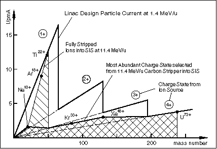
Fig. 1 shows the design
particle current of the new 1.4 MeV/u linac as defined in
front of the gas stripper. The space charge limit of the synchrotron
is expected to range from 4 · 1011 ions
for C6+ down to 4 · 1010
ions for the heaviest particles like U73+ at the standard
injection energy into SIS at 11.4 MeV/u [2].

| Cavity | ||||
| Total length/m | ||||
| Inner diameter/m | ||||
| Energy range/keV/u | ||||
| Max. volt. between electrodes / kV | ||||
| Aperture diam. / mm | ||||
| RF power losses / kW | ||||
| RF power into beam /kW | ||||
| Norm. exit rms emittances x,y/mm mrad, z/keV ns/u |
Taking into account
the particle losses by stripping as well as an expected growth
of the normalized transversal emittances by a factor of 4 along
the whole linac and transport lines the estimated SIS current
needs out of the new 1.4 MeV/u linac are as shown in Fig. 1 by
the shaded area. 25 turns are injected into the effective horizontal
SIS acceptance of 150 ![]() mm mrad, the corresponding filling time
is 100 µs.
mm mrad, the corresponding filling time
is 100 µs.
A frequency of 36.136 MHz was chosen for the new linac, which is one third of the ALVAREZ frequency. This choice allows a good acceleration efficiency along the 1.4 MeV/u section and meets the beam specifications. At the same time the cavity diameters of the IH-DTL are up to 2.03 m which allows a convenient installation in the UNILAC tunnel. Production and in house copper plating are well established for cavities of that size.
Beam dynamics reasons and rf amplifier economy require the RFQ to be designed as one cavity while the IH-DTL consists of two cavities (Fig. 2). These cavities provide maximum voltage gains of 7.7 MV (RFQ), 40.5 MV (IH1), and 42.7 MV (IH2) respectively. Their main parameters are listed in Table 1.
Besides the high current-mode (10 Hz/100 µs pulse train) the new front end linac additionally has to allow operation at rf duty cycles up to 30 % for A/q 26 to continue the original UNILAC operation mode with a 50 Hz/5 ms pulse train out of PENNING ion sources. In that case time averaged heat losses up to 20 kW in the RFQ and up to 50 kW in each IH-DTL cavity have to be removed by cooling water.
As UNILAC was originally
designed for low beam intensities, some modifications along the
whole system will be necessary. The redesign of both stripper
areas including the subsequent charge separation is done at present
[7,8].
The beam will be generated at one of the two preinjector terminals. While the existing two 320 kV terminals and the adjacent beam lines for the 11.4 keV/u beams are identical, in future at least one beam line will be optimized for high current beams from MEVVA and CHORDIS ion sources [9]. Typically ion source beam fractions above 40 % are contained in the selected charge state out of these ion sources. They supplement each other in producing the required beam intensities within normalized emittances of 0.2 mm·mrad for a large number of elements across the whole mass range. Unbunched high intensity ion beam transport shows space charge compensation within a few 10 µs. However a stable beam transport including ion source intensity fluctuations will benefit from a layout which allows for some space charge decompensation along the injection beam line.
It is desirable to
keep the charge and mass separation up to lead isotopes as included
in the actual system furtheron for both beam lines. The low injection
energy of 2.2 keV/u needs a careful optimization of the PENNING
ion source and of the beam transport into the RFQ. Two test stands
are under construction to improve the operation with that type
of ion source.
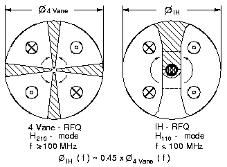
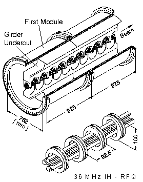
Several designs for low frequency RFQ cavities were developed and partly operated with beam during the last two decades [10,11,12]. After carefully comparing the achievements with the requirements of the High Current Injector it was decided to develop a new structure - the IH-RFQ [13,14]. A simplified cross-section and a comparison with the 4 Vane RFQ are shown by Fig. 3. The design principle is explained by Fig. 4, which shows the first and second out of 10 modules of the 36 MHz IH-RFQ. Main advantages of this structure if compared to other low frequency designs are:
The beam dynamics design and the particle simulations were done at the IAP, Frankfurt University [15]. Table 1 gives the main beam and cavity parameters.
A specific matching problem from the RFQ into the DTL for high A/q beams with high intensity arises from the fact, that the lenses and rebuncher cavities need more space or/and cause large beam envelope oscillations to get the needed focussing strengths while space charge action is controlled more easily by a focussing tool which acts in both transversal planes and longitudinally at the same time. A very compact matcher design study was described in ref. [16]. A six cell RFQ was integrated at the entrance of the IH-DTL cavity to provide both transversal and longitudinal focussing. The now improved matcher design consists of a short quadrupole
doublet immediately behind the main
RFQ, a 100 mm long diagnostic box and a 11 cell adapter-RFQ 'Super
Lens' which is an independent cavity [17]. Its parameters are
given in Table 1.
The total voltage gain of 83.2 MV is distributed on two cavities. This results in convenient rf power levels below 2 MW for each cavity which can be provided by tetrode driven final amplifier stages. Moreover the cavity lengths around 10 m at 36 MHz are short enough to get a sufficient frequency separation between the H111- and the H112-mode [18].
The IH-DTL uses the beam dynamics principle of 'Combined Zero Degree Sections' as operated at the GSI High Charge State Injector and at the CERN Lead Injector successfully [19]. Tank IH1 contains 4 sections while tank IH2 contains 2 sections only (Fig. 5). These sections are transversally beam matched to each other by magnetic quadrupole triplets.
The 1.6 m long coupling section between IH1 and IH2 consists of two magnetic xy-steerer pairs, a 100 mm long diagnostic box which contains a 4 segmented pick up probe and a current transformer, and a magnetic quadrupole triplet with 1.15 m length.
To get aperture diameters of 36 mm for
the first and second quadrupole triplet in IH tank 1 and 48 mm
for all of the other lenses down to the 1.4 MeV/u gas stripper,
a cobalt steel alloy is used for the fabrication of lthe laminated
quadrupoles which guarantees high permeability up to a magnetic
flux density of 2.3 T.
Cavity Design
The principle is shown in fig. 5. Compared to previous IH cavity designs the novel design elements are summarized in the following:
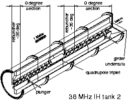
Fig. 5. IH-tank
2 consists of 4 modules. It is housing two combined zero degree
drift tube sections coupled transversally by a magnetic quadrupole
triplet.
The last mentioned modification was not trivial. To get rid of over voltage at the gaps in front and behind of these large drift tubes the detailed studies performed with the MAFIA-code and on a 1:5.88 scaled model were important [18]. The axially extended drift tube stem and the deep cut into the girder opposed to the large drift tube resulted from these studies (fig. 5). The tank diameters and the cavity end geometries were also determined by the MAFIA calculations. For tank IH2 these numbers were verified meanwhile with high consistency by rf model measurements. Moreover the gap to period ratio along that cavity was optimized to get agreement with the voltage distribution as used in the LORASR beam dynamics calculations.
It was also shown
that two capacitive plungers per cavity are sufficient to get
a frequency tuning range Df/f of up to ![]() 5
. 10-3
5
. 10-3
without disturbing the gap voltage distribution.
Their axial distance from the corresponding cavity end wall is
around 1.2 m.
Beam Dynamics
The main beam parameters
and design values of key components are listed in Table 1.
They are derived from calculations with a unbunched 2000 particle
waterbag distribution injected into the RFQ at 2.2 keV/u
and transformed along the RFQ with the PARMTEQ-code [15] and successively
along the matching section and the IH-DTL by the LORASR code.
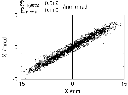
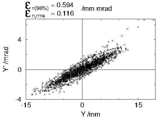
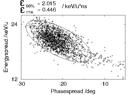
Fig. 6 shows the emittance plots at 1.4 MeV/u, immediately
behind of IH tank 2 at the design current of 16.5 emA and
A/q = 65. The averaged beam power in the 100 µs
pulse corresponds to 1.5 MW, the beam power in the micro
pulse with a 90 % rf phase width of 15 deg is as high as 35 MW.
Particle losses of around 10 % are located in the RFQ while
normalized r.m.s. emittance blow up of a factor 2.2 transversally
and of a factor 3.2 longitudinally occurs mainly in the matcher
and along the first and second zero degree sections of the IH-DTL.
Especially at the design current level the particle density out
of the RFQ becomes very much peaked in the centre of the longitudinal
emittance plane. This is reflected by the fact that along the
matcher and IH-DTL the 20% norm. emittance area is increased by
a factor 3.7, while the 90% emittance area is increased by a factor
2.6 only. Nevertheless the resulting emittance areas at the exit
of the new injector linac are close to the minimum permissible
range of values to get an acceptable beam transport along the
stripper sections and through the 4 ALVAREZ tanks. The space charge
effects are still rather strong for the given beam parameters
along the UNILAC and the transfer line into SIS. The destruction
potential of heavy ion beams is described in ref. [20]. Great
care has to be taken in the development of adequate protection
systems, beam diagnostics and machine operation strategies.
The new frequency 36 MHz is generated by a oscillator which is phase locked to the 108 MHz reference signal of the ALVAREZ. The 36 MHz power splitter has to feed 7 amplifier chains. Four of them have a 200 kW end stage (Super Lens, two rebuncher cavities at 1.4 MeV/u and one debuncher cavity at 11.4 MeV/u) while three chains have an additional 2 MW final stage to feed the RFQ and two IH-DTL cavities.
The 200 kW stages
have grounded cathode circuits while the 2 MW stages are
based on grounded-grid circuits. The operating point during each
rf pulse can be redefined to optimize the transmitter efficiency
and stability for a wide range of rf power levels and beam intensities.
The RFQ tanks are
under construction and delivery to GSI will be in Dec '96. The
IH tanks will be delivered in July '97. The new 91 MV linac will
be installed during the second half of 1998.
[1] Beam Intensity Upgrade of the GSI Accelerator Facility, GSI-95-05 Report.
[2] K.Blasche, B.Franzke, Status Report on SIS-ESR, proc. of the EPAC94, London, vol. 1, p. 133-137.
[3] N.Angert, Status and Development of the GSI Accelerator Facilities, proc. of the 1996 EPAC Conf., Gran Sitges, Spain.
[4] R.Keller, P.Städtke and H.Emig, Recent Results with a High-Current, Heavy-Ion Source System, Vacuum, vol. 36, p. 833-835.
[5] I.G.Brown, Vacuum Arc Ion Sources, Rev. Sci. Instrum. 65(10), p. 3061-3081.
[6] P.Spädtke, H.Emig, C.Mühle, E.M.Oks and I.G. Brown, Development of a Vacuum Arc Metal Ion Source for Heavy Ion Accelerators, see ref. [3].
[7] W.Barth, J.Glatz, J.Klabunde and U.Ratzinger, Space Charge Dominated Beam Transport in the 1.4 MeV/u-UNILAC-Stripper Section, these proceedings.
[8] J.Glatz, B.Langenbeck, A High Duty Foil Stripper System in the Injection Line to the Heavy Ion Synchrotron SIS at GSI, see ref. [6]..
[9] W.Barth, L.Dahl, J.Klabunde, C.Mühle, P.Spädtke, High Intensity Low Energy Beam Transport Design for the New Injector LINAC of the UNILAC, these proceedings.
[10] R.W.Müller, U.Kopf, J.Bolle, S.Arai, P.Spädtke, Experimental Results with a Very-Heavy-Ion RFQ Accelerating Structure at GSI, proc. of the LINAC84, Seeheim, GSI-84-11, p.77-79.
[11] U.Bessler, A.Schempp, T.Sieber, J.Klabunde, P.Spädtke, Experiments with the High Current Spiral RFQ Prototype, these proceedings.
[12] A.Schempp, H.Vormann, H.Deitinghoff, O.Engels, D.Li, Design of a High Current RFQ for U4+, GSI-95-06 Report, p. 24.
[13] U.Ratzinger, K.Kaspar, E.Malwitz, R.Tiede, S.Minaev, The RFQ Section of the New UNILAC Prestripper Accelerator at GSI, see ref. [6].
[14] K.Kaspar, U.Ratzinger, Design of the GSI 36 MHz RFQ Accelerator on the Base of MAFIA Calculations, see ref. [6].
[15] A.Schempp, Design of Compact RFQ's, these proceed-ings.
[16] U.Ratzinger, High Current IH Structures, proc. of the EPAC94, London, Vol. 1, p. 264-266.
[17] U.Ratzinger, R.Tiede, A New Matcher Type Between RFQ and IH-DTL for the GSI High Current Heavy Ion Injector, these proceedings.
[18] B.Krietenstein, T.Weiland, U.Ratzinger, R.Tiede, S.A.Minaev, Numerical Simulation of IH-Accelerators with MAFIA and RF Model Measurements, these proceedings.
[19] U.Ratzinger, The IH Structure and its Capability to Accelerate High Current Beams, Conf. Record of the 1991 IEEE PAC, San Francisco, 91 CH 3038-7, p. 567.
[20] P.Strehl, Thermal Aspects of Beam Intercepting Diagnostic Devices, see ref. [3].