Symmetrical electric field in a coupling
cavity was obtained with a double-feed type coupler in which two
irises couple to symmetrical TM01-mode. To simplify
the structure, J-shaped waveguide was attached to the cavity for
feeding the rf power through the two irises. Good field symmetry
was verified by the perturbation method. The cavity was tested
in maximum surface gradient up to 118 MV/m which was limited by
a klystron performance and not breakdown limit. The field emission
current was measured with Faraday cup and the microscopic field
enhancement factor of 66 was obtained with Fowler-Nordheim plot
and no critical discharge occurred. It was confirmed that the
presented double-feed coupler is capable of handling high surface
gradient more than 100 MV/m.
In next generation linear colliders
in the center of mass energy range of 300~500 GeV, high luminosity
of 1033 ~1034 /cm2/s is required [1].
To obtain high luminosity, it is necessary to accelerate electron
beams maintaining its low emittance. One of the main reason to
cause beam deflection and emittance growth is the asymmetrical
field around the axis because of its coupling iris. A magnetic
field component associated with this asymmetrical field kicks
electron beam in transverse direction. To solve this problem,
different types of double-feed coupler have been proposed and
developed by SLAC[2][3]
and DESY[4].
They have good symmetrical field but the structures are rather
complicated because they use power divider. To simplify the structure,
we developed a new type of double-feed coupler of which J-shaped
waveguide was attached to the cavity as shown in Fig. 1.
In the structure shown in Fig. 1, rf
power is fed by J-shaped waveguide through two irises, which are
located at opposite symmetrical positions around the axis of the
cavity. Rf characteristics were measured as listed in Table 1.
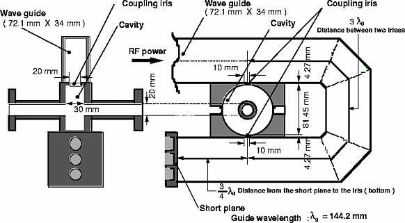
Fig. 1. Double-feed coupler. J-shaped waveguide was attached to the cavity .
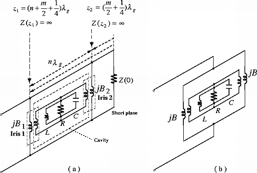
Fig. 2. ( a ) Equivalent circuit model
of the double-feed coupler.
( b ) simplified model.
The principle of the double-feed coupler
is explained with an equivalent circuit model as shown in 2 (
a ). The parallel LCR resonator represents coupling cavity and
the susceptance ![]() and
and ![]() are associated with the irises. Here, we assume no loss in the
transmission line. The impedance
are associated with the irises. Here, we assume no loss in the
transmission line. The impedance ![]() seen
from an arbitrary position
seen
from an arbitrary position ![]() to a short
plane is given as:
to a short
plane is given as:
where ![]() is the
characteristic impedance of the transmission line and
is the
characteristic impedance of the transmission line and ![]() is the guide wavelength. When the irises are located at the position
is the guide wavelength. When the irises are located at the position
![]() (
( ![]() ,
, ![]() ;
integer ) and
;
integer ) and ![]() , the impedance
, the impedance ![]() and
and ![]() become infinite. The susceptance
become infinite. The susceptance
![]() and
and ![]() looking
from the rf source are equal because the distance between two
irises is
looking
from the rf source are equal because the distance between two
irises is ![]() . In this case, we can omit
the impedance
. In this case, we can omit
the impedance ![]() and simplify the equivalent
circuit model from ( a ) to ( b ). Same power is fed in the cavity
from each iris.
and simplify the equivalent
circuit model from ( a ) to ( b ). Same power is fed in the cavity
from each iris.
We chose the integers ![]() and
and ![]() .
.
The field distribution was obtained
by the perturbation method with a dielectric bead ( ![]() ,
spherical, made by macor ) as a perturbation object. To verify
improvement of the field symmetry, it was compared with that in
a conventional single-iris coupler cavity.
,
spherical, made by macor ) as a perturbation object. To verify
improvement of the field symmetry, it was compared with that in
a conventional single-iris coupler cavity.
When a dielectric bead is used, the
deviation of the resonant frequency ![]() is
represented as:
is
represented as:
where ![]() is the
resonant frequency of the cavity,
is the
resonant frequency of the cavity, ![]() the
geometrical factor and equal to 3 in this case,
the
geometrical factor and equal to 3 in this case, ![]() the dielectric constant in vacuum,
the dielectric constant in vacuum, ![]() the
electric susceptibility,
the
electric susceptibility, ![]() the electric
field,
the electric
field, ![]() the volume of a perturbation object
and
the volume of a perturbation object
and ![]() the energy stored in the cavity.
By moving the bead and measuring the frequency shift
the energy stored in the cavity.
By moving the bead and measuring the frequency shift ![]() ,
the field intensity is calculated from equation ( 2 ). The field
distribution was measured by moving the bead from one iris to
the other. The measured field distributions are shown in Fig.
3. The field symmetry in the cavity was better than that in the
conventional single-iris coupler cavity.
,
the field intensity is calculated from equation ( 2 ). The field
distribution was measured by moving the bead from one iris to
the other. The measured field distributions are shown in Fig.
3. The field symmetry in the cavity was better than that in the
conventional single-iris coupler cavity.
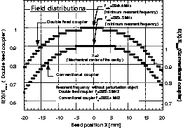
Fig. 3. Field distributions in cavities of the double-feed coupler and a conventional single-iris coupler.
In order to investigate the high power performance, high gradient experiment is performed. Maximum surface gradient, microscopic enhancement factor, momentum distribution of field emission current and vacuum level were measured. A layout of the experimental apparatus is shown in Fig. 4. A 5MW klystron is used as a power source which supplies rf power in the coupler cavity through a waveguide filled with SF6 gas. An rf window separates this waveguide to the other vacuum type waveguide.
Incident and reflected power were measured
with Bethe-hole type coupler and these waveforms are shown in
Fig. 5. The maximum surface gradient ![]() is given as the function of the incident power
is given as the function of the incident power ![]() as:
as:
The incident power is limited by the klystron performance. In this case, the maximum power was limited up to 3.4 MW. The maximum surface gradient of 118 MV/m was obtained without any critical discharges. The break down limit seems considerably higher than this value.
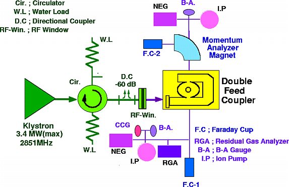
Fig. 4. Layout of the high gradient experiment.
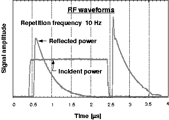
Fig. 5. The waveforms of incident rf power and reflected rf power.
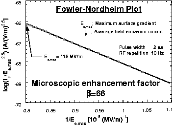
Fig. 6. Fowler-Nordheim plot from which
the microscopic enhancement factor of 66 is obtained.
Microscopic enhancement factor ![]() is obtained from Fowler-Nordheim plot which is given as:
is obtained from Fowler-Nordheim plot which is given as:
 (4)
(4)
where ![]() is the
field emission current,
is the
field emission current, ![]() the work function.
The field emission current was measured with Faraday cup FC-1
and the maximum surface gradient was given by equation (3). The
microscopic enhancement factor of
the work function.
The field emission current was measured with Faraday cup FC-1
and the maximum surface gradient was given by equation (3). The
microscopic enhancement factor of ![]() was
obtained from the Fowler-Nordheim plot as shown in Fig. 6.
was
obtained from the Fowler-Nordheim plot as shown in Fig. 6.
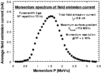
Fig. 7. Momentum distribution of the
field emission current in the coupler cavity.
The momentum distribution of the field
emission current is shown in Fig. 7. The momentum was measured
with the momentum analyzer magnet and the current value was measured
with Faraday cup FC-2 in Fig. 4. As the momentum acceptance ![]() of the system was about 40 %, the maximum momentum of the field
emission current was estimated to be about 2.0 MeV/c. Then the
calculated accelerating field in the cavity was above 60 MV/m.
of the system was about 40 %, the maximum momentum of the field
emission current was estimated to be about 2.0 MeV/c. Then the
calculated accelerating field in the cavity was above 60 MV/m.
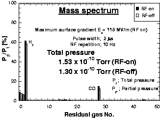
Fig. 8. Mass spectrum of the residual
gases. There
was no critical difference between rf-on case and rf-off case.
No critical discharge occurred.
The vacuum level of 1.53×10⁻¹⁰
Torr was measured with B-A gauge. Mass spectrum of the residual
gas was obtained by a residual gas analyzer as shown in Fig. 8.
There was no critical difference between rf-on case and rf-off
case. It shows that no critical discharge occurred.
Field symmetry was improved by adopting
the double-feed type coupler. The high gradient experiment showed
that it is capable of handling high surface gradient more than
100 MV/m. This type double-feed couplers have already been used
for some accelerating structures at KEK.
The authors wish to acknowledge Prof.
M. Yoshioka, Dr. T. Shintake and Dr. Y. Takeuchi for their continuous
encouragement.
[1] JLC Group, ìJLC-Iî, KEK Report 92-106, December 1992, A/H/M.
[2] R. B. Neal , ì The Stanford Two mile accelerator î, 1968, W. A. Benjamin, inc., 144 - 148.
[3] H. Deruyter, et al., ì Symmetrical double input coupler development î, 1992 Linear Accelerator Conference Proceedings, 1992 August 24-28 Ottawa, Ontario, Canada, 407-409.
XS[4] N. P. Sobenin, et al., ì DESY linear collider accelerating section coupler î, Proceedings of the 1994 International Linac Conference, August 21-26, Tsukuba, Japan 74-76.