In this paper the electrodynamic characteristics
of the 6 meter SBLC accelerating section with constant gradient
are considered. The values of resonant frequencies, longitudinal
and transverse shunt impedances, Q-factor for the fundamental
and first dipole modes were calculated using MAFIA code and also
were measured by small perturbation method with disk and cylindrical
probes. The results measurements and calculations for the first
and last SBLC DLW cells are presented.
Two sets of cells for the input (cell N1) and output
( cell N178 ) ends of 6-m long section Disc Loaded Waveguide of
S-Band Linear Collider ( SBLC DLW ) [1] were fabricated. All measurements
of ElectroDynamics Characteristics (EDC) were carried out by means
of those cell sets since the resonance measuring units were assembled
on the basis of cells with the same dimensions. Before measurements
some calculations were conducted with the using of programs URMEL-T
and MAFIA [2]. To simplify the calculation procedure and obtain
more complete information in particular at
phase shift on some cells there were no rounding. The absence
of rounding decreased the effective shunt impedance. from 45.13
to 43.27M/m for cell N1 and from 61.32 to 58.85M/m for cell N178.
Other EDC were changed insignificantly. But in the case without
rounding we can assemble resonant sections consisting of several
full cells and half-cells at the ends. For such sections with
electrical walls at the ends one can calculate the EDC at the
frequencies corresponding to -mode of the fundamental and hybrid
modes
Experimental studies were carried out with resonant sections consisting of 6 similar cells with dimensions corresponding to the first and the last cells of 6m long SBLC DLW (its first version where 2a for the first cell equals 31,02 mm and for the last one 21,77 mm). Measurement of resonance frequencies, Q-factors and longitudinal and transverse shunt impedance were conducted according to the technique [3]. For the measurement of shunt impedance at dipole mode frequencies a device was developed and fabricated which could provide the relative frequency stability 10-7 in the range from 4 up to 6 GHz The results of EDC measurement for two mentioned resonant sections operating in the fundamental mode are presented in detail for the DLW cell with 2a=21.77 mm . According to the handbook on DLW [3] one for the structure under consideration the following parameters can be predicted: gr2/3=0,0128,

where gr2/3 is group velocity at 2/3 mode,
2/3 is wave length in free space corresponding to 2/3
mode, E0 is first harmonic amplitude of accelerating
field, P is input power, rshII is longitudinal shunt
impedance.
The value of Q was equally 14700. At Q=13200 the value of rsh|| is equal to (633)M/m.
The measured values of frequencies and Q-factors
at those modes are given in Table 1. All the cells were tuned
to the 0-mode frequency with the error 0,1 MHz before measurement
of the longitudinal shunt impedance.
Fourier analysis of the field distributions was carried out for the middle part of the section over three cell length. For =2/3 the relative amplitude of the main harmonic has been determined to be
The form-factor of the bead used for the measurements appeared to be
The electrical field strength parameter for the resonant section of DLW has been defined as
For the traveling wave case the electric field strength
parameter is introduced as ( ) [4] :
As for the parameter it
can be written as
and for one can obtain
.
Note, that at
the cells should be finely
tuned to their own frequency to obtain good field symmetrization.
The longitudinal shunt impedance at the fundamental
mode of DLW first cell was measured with the use of metallic and
dielectric cylinders. The measurements were carried out for 2/3
and modes. The calculation of rsh|| was based
on the determination of the ratio . If
Q-factor was equal 14500, the longitudinal shunt impedance at
2/3 mode was 48.1M/m (measured by metallic bead) and 44-49M/m
(measured by dielectric bead). At the mode these values were 43.5M/m
and 38.8M/m correspondingly.
In the beginning of study of the first dipole mode
EDC for the structure which consists of cells similar to the last
one of SBLC DLW (2a=21.77mm) preliminary individual tuning of
each cell to the frequency of the hybrid wave 0-mode was have
again carried out. It should be noted that even slight defect
of a cell caused arising of not strongly expressed resonance of
the second dipole mode. The resonant frequency of the hybrid wave
was measured in the assembled prototype consisting of 6 tuning
cells. The measured values of frequencies and Q-factors are presented
in Table2.
Experimental data of the dispersion curve for the
first dipole mode SBLC DLW with 2a=31.02mm are shown in Table
3.
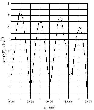
These data were obtained experimentally on the resonant prototype consisting of 3 full specially shaped cells (the cell surface is rounded) and two half-cells without rounding. We have used such a structure because it is not possible to excite the first dipole mode with phase shift in the structure consisting of full cells. The half-cells diameter was determined on the prototype exited at the fundamental mode with 2/3 phase shift. The dispersion relation indicates that -mode and neighboring 3/4-mode have frequencies which differ only by 2.4MHz. It results in complications in the study on the basis of small perturbations method. For obtaining the correct electric field pattern in the prototype, consisting of 3 full cells and 2 half-cells, we have to retune individually the prototype elements with high precision (about 0.02 MHz). Moreover, the choice of perturbing bodies is also limited because maximal perturbation should not exceed 0.5MHz. That limits the directness coefficient of the perturbing body.
The transverse shunt impedance
was determined in terms of the longitudinal shunt impedance
according the formulae:

where k is the wave number in the free space.
Using MAFIA program the values of
and
were obtained for -mode and other
mode of the first dipole wave of the first and last DLW cells.
The knowledge. of
and
values at modes different from the -mode is helpful for the precise
determination of
at frequencies corresponding
to the hybrid wave phase velocity equal to the light velocity.
The results of
calculation by MAFIA code
are in satisfactory agreement.
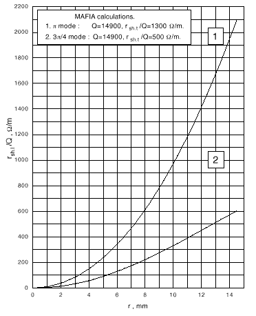
The ratio of the longitudinal shunt impedance to the Q-factor as a function of the distance from the structure axis, obtained with by MAFIA program is shown in Fig.1. The calculations were carried out for the structure, consisting of 3 full cells and 2 half-cells with dimensions 2a=31.02mm, 2b=81.38mm, D=33.33mm, t=5mm. There were no rounding of the disk apertures and cell inner surfaces. It is clear that such a structure differs from one experimentally studied. But this calculation is more simple due to the absence of rounding.
The following results were obtained:
at -mode and
at 3/4-mode.
Similar computations were conducted by means of URMEL-T
program for the structure, consisting of 3 full cells with rounding
and 2 half-cells without rounding. The value of
at -mode had appeared to be 700/m.

Measurements of the transverse shunt impedance in
the structure, consisting of three full cells and two half-cells,
were carried out by means of disk and cylinder shaped perturbing
bodies. The form-factor of disk shaped perturbing body with diameter
3.5mm and thickness 0.5mm was . Calculations
of experimental data with using of the fundamental harmonic have
given the following result: rsh/Q=(63960)/m. At Q=13000
the value of transverse shunt impedance rsh=(8.30.8)M/m.
Similar measurements were carried out with cylindrical perturbing
body which had length 6mm, diameter 0.7mm, form-factor kEz=0.944x10⁻¹⁹m2s/,
and directness coefficient kd = 71. In this
case we have the result: rsh /Q=(805110)/m. At Q=13000
rsh=(10.41.5)M/m.
Comparison of experimental and calculated values of the transverse shunt impedance at mode (Table 3) shows the experimental ones are somewhat lower like it was for the case of SBLC DLW with 2a=21.77mm
The transverse shunt impedance values calculated by MAFIA code (last version) in DESY was 9.9 M/m for cell with 2a=31.02mm and 14.9M/m for cell with 2a=21.77mm. The experimental result for cell with 2a=21.77mm was equal 11.5M/m.
| cylinder bead | |||

We investigated the electrodynamics characteristics
of the SBLC accelerating structure. The resonance frequencies,
Q-factor, longitudinal shunt impedance were measured at the fundamental
and first dipole modes for the first and last cells of DLW. The
values of transverse shunt impedance was measured by small perturbation
method with disk and cylindrical probes and also were calculated
by MAFIA code.
[1]. N. Holtkamp, T. Weiland et al. „ Structure Work for an S-band Linear Collider „ Proc. of 15 International Conference on High Energy Accelerators, 1992, v.2, pp. 830-832.
[2]. R.klatt, F. Krawczyk, W.R.Novender, C.Palm, T.Weiland, B.Steffen, T.Barts, M.J.Browman, R.Cooper, C.T.Mottershead, G.Rodenz, and S.G.Wipf, in Proc. 1986 Linear Accelerator Conf., SLAC-303, p.276 (1986).
[3].O.Valdner, N. Sobenin et al. „ Handbook of Disk-loaded Waveguide „ , Moscow, Energoatomizdat, 280 pages, 1991.
[4]. N. Sobenin, B. Zverev, „ Electrodynamics Characteristics of Accelerating Resonators „ ,Moscow , Energoatomizdat, 220 pages, 1993
.