![]()
![]()
N.P. Sobenin, S.V.Ivanov,V.E. Kaljuzhny, D.V. Kostin, O.S.Milovanov,
A.N.Parfenov,A.A. Zavadzev, S.N. Yarigin
Moscow Engineering Physics Institute, Kashirskoe Shosse 31, Moscow, 115409,
Russia
M. Dohlus, N. Holtkamp
Deutsches Electronen-Synchrotron, DESY, Notkestrasse 85, 22607 Hamburg,
Germany
An application of the symmetrical SBLC section coupler for the Higher Order Mode (HOM) damping was investigated. The demands to the own frequency and Q-factor of the coupler at HOM have been obtained on the basis of an equivalent scheme of the Disk Loaded Waveguide (DLW) with this coupler. HOM field amplitude distribution along the structure and an influence of the coupler cavity own frequency on the HOM field distribution were investigated. The influence of some elements inserted in the coupler cavity to obtain the necessary frequency shift between fundamental and hybrid modes was studied.
Excitation of the trapped high order modes in travelling wave accelerating structures is a big problem to save the required beam parameters. There are various conceptions of diminishing the trapped modes influence on the beam dynamics in the DLW accelerating structures.
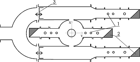
Fig.1. Plan of the investigated input coupler: 1- tuning pins; 2 -absorbing loads; 3 - short-circuiting plungers.
One more technique of the trapped modes damping may be the use of the symmetrical coupler for a 6 meter SBLC accelerating structure [1]. It has been designed on the basis of the input coupler with additional coupling holes for withdrawing the Y-polarised mode (see Fig.1). It is necessary in addition to the HOM damping to secure the coupler matching at the operating frequency. Works in that direction were carried out on the SBLC accelerating section [2]. We try to study some questions connected with the conception of the trapped modes damping SBLC by the input coupler in an initial 1 meter part of the SBLC accelerating section.
The analysis of the hybrid waves excitation in the SBLC section was carried out on the basis of an equivalent scheme of DLW at HEM11-modes, which is shown in Fig. 2.
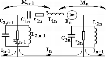
Fig.2. Equivalent scheme of a DLW at hybrid modes.
The series branch (L1n , C1n , r1n) represents the existence of the E11-mode electromagnetic field. On one hand the coupling between cells is realised by magnetic field that is represented by mutual inductance Mn . On the other hand there is resonance type coupling by means of the H11-mode electromagnetic field that is represented by parallel branches (L2n , C2n , r2n ). The cell excitation is modelled by introducing of complex e.m.f. En into the series branch.
It is more convenient to operate with the following parameters expressed in terms of L, C, r:
 (1)
(1)
By using these parameters one can obtain the equations set with respect
to complex values ![]() n
Note that in the equivalent scheme the number of parallel branches is equal
to N+1 , whereas that of series branches equal N, where N
is the number of cells in the section. Both first and last parallel branches
(indexes 0 and N+1) are introduced for modelling a beam pipe in
the input and output couplers.
n
Note that in the equivalent scheme the number of parallel branches is equal
to N+1 , whereas that of series branches equal N, where N
is the number of cells in the section. Both first and last parallel branches
(indexes 0 and N+1) are introduced for modelling a beam pipe in
the input and output couplers.
Voltages across the capacitive element C1n( ![]() zn
) and C2n (
zn
) and C2n ( ![]() rn
) are related to
rn
) are related to ![]() n
by the expressions which are found by using the equivalent scheme.
n
by the expressions which are found by using the equivalent scheme.
Modelling of the input coupler was realized by means of addition of
the coupler cell coupled with first cell of DLW. Frequency f1C
and Q-factor Q1C of this additional cell are chosen
in such a way that we should have: the travelling waveregime in the DLW
consisting of cells similar to the first one; the operational frequency
of the travelling wave regime being fop,; the phase shift
per cell at this frequency being ![]() op.
op.
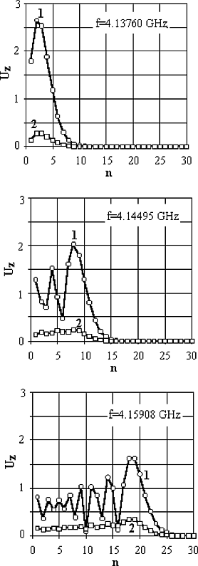
Fig.3. Cell voltages Uz versus cell number n cells
By using the equivalent scheme shown in Fig.2 cell voltages Uz were
calculated as function of the cell number at different frequencies for
first 30 cells of the SBLC accelerating section (see Fig. 3) [3]. Curves
at these graphs corresponds the cases when input coupler is mismatched
with first accelerating section cell (curve 1) and matched with DLW (curve
2) at the frequency fop=4.151 GHz (![]() op=95
0 ). Excitation of the accelerating section has been simulated by introduction
of e.m.f. into the cells 2, 8 and 18 at the frequencies 4.13760, 4.14495
and 4.15908 GHz correspondingly. The series branch resonant frequency and
Q-factor of this brunch were obtained f1c=4.846777 GHz
and Q1c=14.677. These values correspond to the lowest
resonant frequency of coupler cell fc=4.152224 GHz and
it’s Q-factor Qc=160.
op=95
0 ). Excitation of the accelerating section has been simulated by introduction
of e.m.f. into the cells 2, 8 and 18 at the frequencies 4.13760, 4.14495
and 4.15908 GHz correspondingly. The series branch resonant frequency and
Q-factor of this brunch were obtained f1c=4.846777 GHz
and Q1c=14.677. These values correspond to the lowest
resonant frequency of coupler cell fc=4.152224 GHz and
it’s Q-factor Qc=160.
One may see in Fig.3 that the matching of the coupler at the hybrid mode reduces the amplitude of electric field more than five times in broad frequency band. The analogous results for DLW with constant gradient but without a coupler was presented in a paper [2].
The trapped modes were studied in initial 1 meter part of the real section
with the symmetric coupler matched to the structure at the fundamental
mode. Measurements were carried out by the small perturbation method with
moving a thin cylindrical body (0.1 mm diameter and 8 mm length) along
the accelerating structure at the distance 3 mm from the symmetry axis.
The obtained field distributions are shown in Fig.4. It is seen how the
HOM fields are being trapped in the constant gradient structure if nothing
is done on their damping. The first trapped mode (F=4130 MHz) occupies
five initial cells and has a ![]() -like
mode distribution. With this there is no a longitudinal field component
in the coupler cavity. The last mode fully trapped in the structure has
the frequency F=4161 MHz. In this case the
-like
mode distribution. With this there is no a longitudinal field component
in the coupler cavity. The last mode fully trapped in the structure has
the frequency F=4161 MHz. In this case the ![]() -like
mode occupies from 24 to 30 cells and is being transformed along the structure
toward the input coupler where at this frequency the field is just beginning
to show up.
-like
mode occupies from 24 to 30 cells and is being transformed along the structure
toward the input coupler where at this frequency the field is just beginning
to show up.
At higher frequencies (F=4164-4194MHz) the field penetrates into the coupler cavity and has the amplitude which is comparable with that in the neighbouring cells, but at that p-like mode should be in cells with number more than 30 (see Fig.4). At frequencies higher than 4194 MHz the field amplitudes are reduced in the first cells.
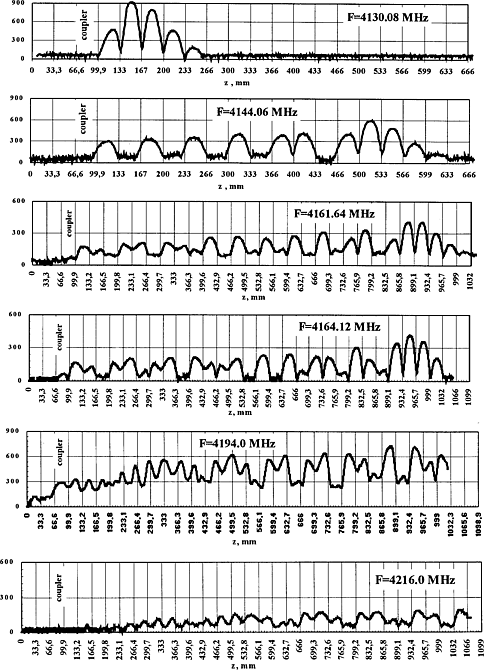
Fig.4. The longitudinal electric field amplitude distribution (in units) in the 30 cells’ SBLC structure.
It means that at those frequencies the section initial part itself begins to trap the dipole modes.
Hence, it is clear that the own frequencies of TM11-type dipole modes of the coupler cavity differ from those of SBLC structure first cells and supposedly lie in the frequency band 4164-4194 MHz and higher. So for providing the coupling of the first dipole modes with the input waveguides through the coupler cavity it is necessary to correlate the coupler cavity dipole modes frequencies with those of the section first cells.
The influence of the coupler frequency on the HOM field distribution was studied with the structure having the coupler, which allowed to vary the own frequency. Fig. 5 presents the field amplitude in the unchanged coupler (a) and in the coupler with reduced own frequency on 30 MHz (b). One can see that the coupler cavity has its influence on the field distribution at this frequency. By means of changing the distance from the X-axis to the Y-junction (i.e. the short-circuiting plane position for the dipole modes) and using the tuning pins (see Fig.1) the Q-factor value was reduced from 8000 to 2000-4000 over the frequency band about 20 MHz. The obtained Q-factor dependencies on the frequency band for minimal Q-values at certain frequencies 4152 MHz (a) and Mhz (b) of the X-polarisation are shown in Fig.6.
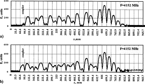
Fig.5. Electric field amplitude depends on frequency.
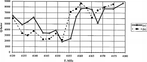
Fig.6. External Q-factor depends on frequency.
In case of hybrid coupler with forth coupling slots for the dipole modes of both polarizations the coupler cavity own frequency is decreased by the value which is more than required one. Here the different width of the coupling slots would result in the discrepancy of the coupler own frequencies for one dipole mode with different polarizations by about 50- 70 MHz. It is demonstrated in Fig.7, where one can see that it is possible to reduce the external Q-factor value of the trapped modes with Y-polarization (a-at frequency 4145MHz and b- at 4152MHz) whereas the Q-factor of the modes with X- polarization is not changed(c).
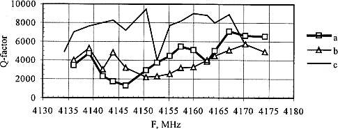
Fig.7. External Q-factor depends on frequency.
The major problem consists in large difference between the coupler cavity own frequencies for the same mode with X and Y-polarizations. Such a problem can be solved if the dipole modes symmetry in the coupler cavity is rejected while the field symmetry for the fundamental mode is kept unchanged. It is realized by means of a replacement the matched load only in one port for the X-polarization. In this case we provide the required drop in the trapped modes Q-4146 factors for both polarizations in three time over the frequency range from 4130 MHz to 4160 MHz by changing the coupler parameters.
Another approach to match the coupler at the fundamental and hybrid modes simultaneously consists in to study the influence of some elements inserted inside the coupler cavity. This problem is to be solved by combining calculations of structures and experiments of prototypes and it is now under solution.
[1]. N.P..Sobenin, S.V.Ivanov, V.E.Kaljuzhny, O.S.Milovanov, A.N.Parfenov, S.N.Yarigin, M.Dohlus. N.Holtkamp, “Design and Performance of Symmetric High Power Coupler for 6 Meter S-band Linear Collider Accelerating Section”. DESY M 94-11, p32 (1994)
[2]. G.V.Romanov, S.N.Ivanov, M.Dohlus, N.Holtkamp, “Some Remarks on the Location of Higher Order Modes in Tapered Accelerating Structures with the Use of a Coupled Oscillator Model”. Proc. 1995 Particle Accelerator Conference and International Conference on High-Energy Accelerators., p2345.v.4.(1996)
[3] N.Holtkamp, T.Weiland et al. “Structure Work for an S-0 band Linear Collider” Proc. of 15 International Conference on High Energy Accelerators. , p830,v.2,(1992)