A.V. Aleksandrov, M.S. Avilov, P.A. Bak, O.Yu. Bazhenov,
Budker INP
Yu.M. Boimelshtein, A.G. Chupyra, R.Kh. Galimov, K.V. Gubin,
N.S. Dikansky, I.V. Kazarezov, O.V. Koroznikov, A.N. Kosarev,
N.Kh. Kot, D.Ye. Kuklin, A.A. Kulakov, N.A. Kuznetsov,
P.V. Logatchev, P.V. Martyshkin, L.A. Mironenko, A.V. Novokhatski,
V.M. Pavlov, A.M. Resakov, Yu.I. Semenov, A.N. Sharapa, A.V. Shemyakin,
S.V. Shiyankov, B.A. Skarbo, A.N. Skrinsky, Yu.F. Tokarev, S.B. Vasserman
630090 Novosibirsk, Russia
The work on the construction of the
![]() factory complex is in progress at Budker INP.
For an effective operation of these machines the injector
complex is designed. It consists of a preinjector
for the production of
factory complex is in progress at Budker INP.
For an effective operation of these machines the injector
complex is designed. It consists of a preinjector
for the production of ![]() and
and ![]() bunches and
their acceleration up to an energy of 510 MeV,
and a damping ring. This paper presents the general scheme
and the current status of the preinjector.
bunches and
their acceleration up to an energy of 510 MeV,
and a damping ring. This paper presents the general scheme
and the current status of the preinjector.
The main preinjector parameters are given in Table 1.
The preinjector output energy
of 510 MeV is an operation energy of the ![]() - factory
of the VEPP-5 complex [1]. A number of (
- factory
of the VEPP-5 complex [1]. A number of ( ![]() )
) ![]() electrons and positrons per second is required to provide
for a simultaneous operation of the
electrons and positrons per second is required to provide
for a simultaneous operation of the ![]() - factory and
the whole VEPP-5 complex at designed luminosities.
- factory and
the whole VEPP-5 complex at designed luminosities.
The preinjector main components are shown in Fig. 1.
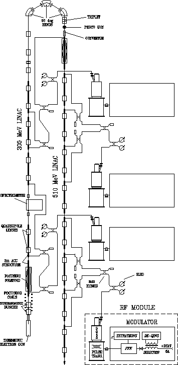
The preinjector comprises a thermionic electron gun, a subharmonic buncher,
a 300 MeV electron linac, a ![]() isochronous turn,
a conversion system, an RF photogun, and a main 510 MeV linac
[2, 3].
isochronous turn,
a conversion system, an RF photogun, and a main 510 MeV linac
[2, 3].
The thermionic 200 kV triode gun delivers 2 ns pulse current of 10 A.
The emittance of the beam is less than ![]() .
.
This bunch comes to the subharmonic buncher operated at
the 16th subharmonic of the basic frequency of 2856 MHz.
The buncher contains two quarter-wavelength cavities with drift gaps.
The transverse focusing of the beam is realized
with the help of the longitudinal
magnetic field produced by current coils, placed around
the cavities. Such a bunching system provides a short intensive
beam, 18 ps long, at a low initial gun current. The short bunch
length is needed to provide a small energy spread ( ![]() )
during a further acceleration.
)
during a further acceleration.
The first linac consists of 5 accelerating sections and
produces an intensive 300 MeV electron bunch for the positron
production. The second linac includes 9 accelerating sections
and accelerates both positrons after the conversion system
and the electron bunch created by RF photogun up to an energy of 510 MeV.
The accelerating sections are 3 m long and have a constant
impedance structure operating at a travelling wave ( ![]() ).
The transverse focusing of the bunch along the linacs is realized
by the solenoid field at the first sections of each linac and two
quadrupoles in each of the other sections. The accelerating gradient
in the first sections of each linac is 25 MeV/m, and in
the other sections it is up to 18 MeV/m.
).
The transverse focusing of the bunch along the linacs is realized
by the solenoid field at the first sections of each linac and two
quadrupoles in each of the other sections. The accelerating gradient
in the first sections of each linac is 25 MeV/m, and in
the other sections it is up to 18 MeV/m.
The 300 MeV electron bunch passes through a ![]() isochronous bending system in a horizontal plane.
The bending system consists of three
isochronous bending system in a horizontal plane.
The bending system consists of three ![]() bending
magnets and 4 quadrupole lenses.
This system provides the transportation of the bunch with an energy
spread of
bending
magnets and 4 quadrupole lenses.
This system provides the transportation of the bunch with an energy
spread of ![]() with an insignificant increase in the bunch
transverse size. After that, the triplet focuses the bunch
at a converse target (the conversion constant is higher than
with an insignificant increase in the bunch
transverse size. After that, the triplet focuses the bunch
at a converse target (the conversion constant is higher than ![]() ).
).
Typically, (approximately 98% of the total time) the preinjector produces positrons to store a required number of particles in the damping-ring. For the electron beam production, one-time injection is enough. The RF photogun placed between the focusing triplet and the converse system is used for this purpose. In this case, it is needed just to remove the target without readjustment of the focusing system. In future, it is planed to obtain polarized electron bunches from the photogun.
The 14 accelerating sections are powered by 4 RF modules based on S-band klystrons 5045 (SLAC, USA). A SLED system permits to obtain the necessary gradients of accelerating fields. The output power of SLED is fed to three or four accelerating sections. In order to maintain the reliable capturing, the first 300 MeV and the first 510 MeV linac sections have a high accelerating rate. It is attained by applying half of the RF power from the corresponding klystron to these sections, then the second half of this power is divided equally between two regular sections. The power of the other two klystrons is divided half-and-half between four regular sections. After SLED the power is divided by 3 dB hybrids.
At present the tests of the first RF module are done, and the experiments on the linac prototype at a frequency of 2797 MHz have been started.
The RF module consists of a 5045 klystron and a high voltage pulse modulator. The high voltage pulse for the klystron is produced by the modulator made at the Budker INP. The modulator is a conventional line type modulator with an oscillatory charge of a pulse forming network (PFN). It consists of a high voltage power supply, a charging choke, PFN and a thyratron switch [4]. During a joint klystron-and-modulator test the control and the klystron protection systems were also tested. The RF module operation was stable for different values of the input RF power and amplitudes of the high voltage pulses at a repetition rate from 1 to 50 Hz.
Now the assembly of the second modulator for the next RF module is under commissioning, the tests of its separate elements are in progress.
The preinjector prototype is built to perform simultaneous tests of the main preinjector elements at a high output power level (see Fig. 2).
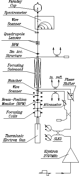
The electron beam formed in the thermionic electron gun
enters the short disk-loaded
bunching section and then the accelerating structure.
The bunch transverse focusing
is the same as in the first linac of the preinjector:
the set of focusing coils
and one solenoid.
The accelerated beam then enters either a ![]() spectrometer
or a Faraday cup.
spectrometer
or a Faraday cup.
The RF power for the prototype is produced by a KIU-12 klystron
(2797 MHz operating frequency, 2.5 ![]() s pulse duration, output
pulse power up to 20 MW) and a power compression system.
The required phase shift between the accelerating structure
and the buncher is carried out by the phase shifter at a
high power level. The phase shifter is made of a cut waveguide
which could be compressed mechanically. The power is delivered to
the buncher through a matched coupler and a retuning attenuator.
s pulse duration, output
pulse power up to 20 MW) and a power compression system.
The required phase shift between the accelerating structure
and the buncher is carried out by the phase shifter at a
high power level. The phase shifter is made of a cut waveguide
which could be compressed mechanically. The power is delivered to
the buncher through a matched coupler and a retuning attenuator.
Before the assembly of the prototype all its elements were preliminarily tested.
The prototype of the termionic 100 kV triode gun is able
to produce 2 ns pulses with a pulse current of up to 2 A.
The emittance of the beam is less than
![]() and the transverse size at
the crossover after adjusting the lenses is 0.5 cm.
and the transverse size at
the crossover after adjusting the lenses is 0.5 cm.
The beam position and the beam profile monitors are tested and calibrated using a 100 kV electron beam from the electron gun.
The buncher section of the prototype consists of 4 coupled
cylindrical cavities and operates on the backward travelling wave
( ![]() ) of the main prototype frequency [5].
The buncher is matched to the feeding waveguide with VSWR better than 1.1.
) of the main prototype frequency [5].
The buncher is matched to the feeding waveguide with VSWR better than 1.1.
The accelerating section of the prototype is a 3 m long
disk-loaded structure of a constant impedance operating on the
travelling wave ( ![]() ). The obtained VSWR value at 2797 MHz is not
worse than 1.02, and less than 1.2 in the
frequency range
). The obtained VSWR value at 2797 MHz is not
worse than 1.02, and less than 1.2 in the
frequency range ![]() 13 MHz.
13 MHz.
The Faraday cup is designed for measuring the total charge of short bunches after the first section of 300 MeV accelerator.
The high power tests of the power compression system are done at
the prototype operating frequency. The compressor is SLED-like
(3 dB hybrid and two resonators which operate at a ![]() mode).
The resonator diameter and length are 196 mm and 359.6 mm respectively.
The resonator has a precise tuning device. The side wall of
the resonator is a thing disk which can be bent
by means of a regulating screw, the quality factor
of resonators
mode).
The resonator diameter and length are 196 mm and 359.6 mm respectively.
The resonator has a precise tuning device. The side wall of
the resonator is a thing disk which can be bent
by means of a regulating screw, the quality factor
of resonators ![]() , the coupling coefficient
, the coupling coefficient ![]() .
The pulse durations of the master oscillator and the
output SLED were 2.5
.
The pulse durations of the master oscillator and the
output SLED were 2.5 ![]() s and 0.5
s and 0.5 ![]() s, respectively.
The power step-up ratio (
s, respectively.
The power step-up ratio ( ![]() ) of
the input pulse power of 10 MW is obtained.
) of
the input pulse power of 10 MW is obtained.
At the present time the prototype of the RF photogun with a GaAs
photocathode is complete [6].
The operating frequency of the prototype is 2797 MHz.
The vacuum of ![]() torr is reached.
The input RF power during the first tests is about 1 MW,
which corresponds to 500 kV/cm of the field amplitude in the RF cavity.
torr is reached.
The input RF power during the first tests is about 1 MW,
which corresponds to 500 kV/cm of the field amplitude in the RF cavity.
The assembly of the master oscillator system is in progress.
The system consists of a generator-synthesizer operating at the 32th
subharmonic (89.25 MHz) of the main linac frequency (2856 MHz), RF pulse forming
amplifiers feeding 2 quarter-wavelength cavities of the subharmonic buncher
(178.5 MHz, 16th subharmonic of main linac frequency)
each at a peak power of 20 kW,
and amplifiers for 4 RF modules provide a power of up to 1 kW each
with a ![]() fast phase switch at a frequency of 2856 MHz.
fast phase switch at a frequency of 2856 MHz.
The manufacture of the waveguide elements, including 4 systems of
power compression at a frequency of 2856 MHz, quadrupole lenses, correctors
and ![]() bending magnets of the preinjector is in progress.
bending magnets of the preinjector is in progress.
A dedicated high-vacuum technology area for the series production of preinjector accelerating sections is presently under commissioning.