The timing stability required for the electron source of the pre-injector is determined by the energy acceptance of the KEKB rings. The jitter requirements for the gun pulse itself are somewhat mitigated by the subsequent bunching process. A system by which a beam trigger stability of 3s ª 20 ps is achieved is described, and the method to estimate the phase jitter of the accelerated beam from the energy jitter is discussed.
The KEK 2.5-GeV Linac which is presently being upgraded will provide beams of 8 GeV electrons and 3.5 GeV positrons for direct injection into the KEKB rings[1]. The energy acceptance of the rings is 0.5%, which places constraints on both the drift and the jitter in the energy of the injected beams. This paper discusses the manner in which the energy of the injected beams will be controlled to meet the requirements of the KEKB rings, with emphasis on the energy jitter.
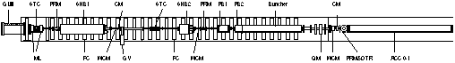
The PF Linac pre-injector has been described elsewhere[2]. The half of the pre-injector is shown schematically in Fig. 1. A 119-MHz subharmonic buncher (SHB1) has been installed last January between the electron gun and a 476-MHz subharmonic buncher (SHB2) to produce S-band single-bunch beams with better bunch purity. A fast grid pulser located near the cathode of the triode gun produces an electron pulse of up to 15 A in a 2 ns pulse. The electron bunch length is first reduced by two pulsed RF cavities operating at respectively the 24th and the 6th subharmonics of the primary 2856 MHz of accelerating RF, then further compressed by two S-band prebunchers and a buncher. The fully bunched beam emerges at the end of the pre-injector with an energy of about 40 MeV, where the beam is momentum analyzed with a 90_-bending system.
The energy of a particle varies as cosq , where q is the angle between the particle and the negative crest of the RF. The buncher of the PF Linac consists of two parts: a bunching section of 6 sells with gradually different phase velocities and a accelerating section of 29 cells with a phase velocity of the speed of light, where bunched electrons are accelerated at a large phase, typically q =40_. Furthermore a short bunch of high intensity must be positioned several degrees ahead of the crest of the accelerating RF in order to minimize the resultant energy spread.
If a particle is accelerated at an angle q0
in the accelerating section of the buncher and then at an angle
q1 in the following
accelerating sections, the resultant energy of the particle becomes
Ej = E0 cos(q0+dqj)
+ E1 cos(q1+dqj)
at any position along the beam line of the linac. Then the energy
jitter, dej = dEj
/Ecenter is given by
![]() (1)
(1)
where dqj is the jitter in the RF phase relative to the beam position. Consequently the deleterious effects of dqj grow as q0 and q1 increase. At the end of the linac where E0 << E1 , the energy jitter is given approximately
dej = dqj tanq1. (2)
Typically q1 is set to about 10_ for the 10-nC beam. If the phase jitter dqj is 1 ps, the energy jitter becomes as large as 0.3% at the end of the linac. Inevitably the phase jitter should be no more than 1 ps to meet the energy acceptance of 0.5% of the KEKB rings even if the energy compressing system is introduced.
Then it becomes important how to measure accurately the phase
jitter as small as 1 ps. Because of large q0
and q1, in the pre-injector
the phase jitter dqj can easily
be estimated by measuring the energy jitter dej
at the exit of the pre-injector.
Any timing change of the beam relative to the accelerating S-band phase results in a beam energy change. Thus, beam timing stability is required to avoid excessive energy jitter or drifts.
Within the first few centimeters of the buncher section the electrons become fully relativistic and subsequently do not change their timing relative to a speed-of-light signal. However, before becoming relativistic the beam is susceptible to timing changes of several origins.
From the bunching process, three potential sources of jitter in
the timing of the accelerated electron pulse can be identified:
trigger timing jitter; grid pulser instability; and RF phase jitter
in the source bunchers. The first two items give the same effect
to the souce pulse. As far as in the pre-buncher the effect of
the last item is thought to be small, since the accelerated beam
position is determined by the bunchers reletive to the RF, which
is supplied from a klystron except for SHBs. Therefore changes
in phase relative to the beam can be the result of a shift in
the timing of the electron bunch itself.
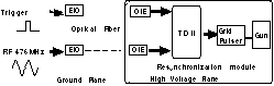
The basic timing trigger for the grid pulser is a trigger derived from the PF Linac timing system. The problem from the outset has been to place this timing signal on the gun high voltage deck without loss of stability. The fiber optical link which has been used was introducing a jitter of several ten picosenond ( 3s = 60 ps ). While it is expected to be possible to transmit the trigger with this improved link which have the required stability, this time as a trial, we placed a CW RF signal (476 MHz) on the high voltage deck where the trigger was resynchronized.
The fiber optical link is shown schematically in Fig. 2. The link utilizes about 50 m of a 100-m graded-index fiber optical cable. A high speed ECL circuit (TD2) was used to resynchronize[3]. With this new link, no timing jitter can be detected in the output of the TD2 above 20 ps threshold of the measuring instrumentation. But of cause at q1 =10_, an energy change of 0.3 % is produced at the end of the linac when the timing jitter of the accelerated gun pulse shifts by only 1 ps. Fortunately the timing jitter at the gun output is mediated by the bunching process itself.
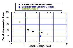
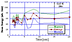
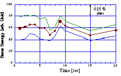
The overall bunch compression ratio is typically between 50 and 100 as is shown in Fig. 3, which varies depending on both the tuning conditions of the bunching system and the beam charge. The fully bunched beam of 10 nC emerges at the end of the pre-injector with an energy of about 40 MeV, compressed into a bunch length of about 13 ps. Since the bunch compression ratio decreases as the beam charge increases, it becomes difficult to stabilize the energy of the high current beams.
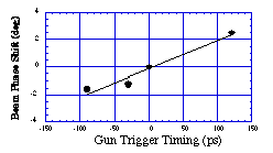
Energy shift of a beam of 10.5 nC was measured at the end of the pre-injector as a function of timing changes introduced in the electron gun trigger circuit. Substituting the measured energy shift into Eq. (1), we obtain the phase shift of the beam in Fig.4
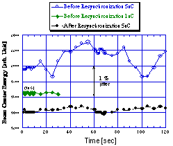
The beam energy has been measured by a 90_-bending magnet system at the end of the pre-injector. A vidicon camera is used to view the beam hitting a fluorescent screen in vacuum at the exit of the analyzer where the dispersion is well known. The video is digitized in 2-dimensions to determine both the centered position and the width of the energy spectrum. When a beam charge was as low as 1 nC, the beam was stable and the energy jitter was not seen on the screen monitor. When the beam charge, however, was increased to 5 nC, the energy jitter of ± 200 keV (± 0.5%) was observed before resynchronizing the beam trigger. By resynchronization the timing jitter deceased to less than 20 ps, the energy jitter has been improved to ± 0.12% as listed in Table 1.
Phase jitter dqj relative to the beam can be calculated from the measured energy jitter dej using Eq. (1). On the other hand, from the timing jitter dtj, the phase jitter dq'j is estimated from the relationship of Fig. 4. The obtained values are well agree in each case, which indicates that energy jitter of the beam is due to the timing jitter of the electron bunch itself as far as pre-injector is concerned.
The fact the the phase jitter was reduced to the required level
has been comfermed by accelerating a beam to the end of the linac.
Energy changes of a 0.5 nC beam were measured with two conditions.
It was actualy observed that before being resynchronized the beam
energy was changing from every pulse to pulse. After being resynchronized,
although residual drift exists in the beam energy, the fast energy
jitter disappeared as being seen in Figs. 6a and 6b, which is
consistent with the phase jitter (3s
= 0.12_) calculated from measured energy
and timing jitter.
Table 1. Phase jitter dqj, dq'j calculated from measured
energy and timing jitter dej, dtj
respectively.
|
|
|
| |
By resynchronizing the beam trigger, it was comfirmed that the
fast jitter of the beam energy from pulse to pulse is due to the
timing jitter of the source, and reduced to the required level
for the KEKB Linac.
[1] A. Enomoto, "Upgrade to the 8-GeV Electron Linac for KEKB", this proceeding
[2] S. Ohsawa et al., "High-Intensity Single-Bunch Beam of the PF 2.5-GeV Linac", Proc. 1994 Int. Linac Conf., 193
[3] K. Ishii, "Digital Delay CAMAC Module with 550 Mhz Preset
Counter (TD-2), KEK 83-14 , 1983, A/I