Concept of parallel electrical circuit was applied
to microwave structures and resulted in multibeam or quasi-hollow
beam structure (MBS) concept [1]. The proposed concept allows
to modify magnetically or electrically coupled periodic microwave
structure into the proposed multibeam or hollow beam structure
and can be used for any charged particles. Concept analysis and
some results were presented at EPAC96 conference. A prototype
with four beams - four beam structure (FBS) based on a side coupled
structure has been studied both theoretically and experimentally
[2]. A number of applications is expected for this concept. It
permits to transmit higher beam current in multiple beams compared
to a single beam current which is restricted due to space charge
limitations, especially at higher frequency. First prototype of
the designed FBS is built in X-band. 10 cm long electron beam
head is designed for 1.2 MeV electron energy, 1 A total electron
beam current and 1 kW average beam power. Various applications
in microwave tube technique are studied.
An idea of building microwave linear accelerators
in a frequency range close to and beyond 10 GHz has lately become
very popular both for high energy and portable accelerators. However,
difficulties of this "state-of-the-art" technique such
as manufacturing and tuning of microwave cavities become much
more complicated at 10 GHz and higher compared to S and L band.
Operating at higher frequency permits a reduction
in outline dimensions and weight of the final package. However,
in higher frequency ranges one faces a problem of beam current
restriction among a number of other complications. Beam current
is restricted by physical aperture size due to space charge limitation
and, in commonly used structures, it is difficult to exceed this
limitation of approximately 109 1/cm3 without
affecting structure efficiency and energy gain.
Multiple or hollow beam concept for microwave structure
design is proposed [1] to expand range of beam current which could
propagate through the structure. Exaple of MBS design is shown
in Fig.1, 2. MBS permits exceeding the space charge limitations
due to reduction of aperture size at high frequency observed,
for example, in X-band.

Beam cross section at radius R is shown as quasi-continuous,
though it could be built of multiple small apertures.

The proposed structure could also be used to increase energy gain for the same linac length in a mode of multiple pass operation.
Energy gain will be increased in proportion to N1/2,
where N is number of beam passes, assuming that we use the same
power source and structure volume grows proportionally to N. Therefore,
with four passes, energy gain would be two times higher, with
16 - four times higher, etc. Bending magnets could be used to
bend the beam 180 degrees.
Potential application of the proposed concept and
the corresponding variations of structure design could be found
in many areas where accelerators are used. We can foresee various
commercial applications, such as non-destructive testing, sterilization,
etc. Concept could be applied to design of microwave amplifier
tubes. Hollow beam instabilities have been studied and observed
by Kyhl and Webster at low energies (<100 keV) for TWT[3] applied
to traditional structures with beam concentrated in the center.
One of the ideas, expressed in the accelerator physics community
is to develop a "table-top" FEL for commercial applications
with an acceptable price range. X-band accelerator for 9 - 13
MeV is a potential source for that application. The proposed system
seems also to be attractive for devices using beam-beam interaction.
The coupled circuits model and microwave theory was
used to analyze one of the simple realizations of the proposed
concept. An FBS cavity was designed which is capable of accelerating
four parallel beams, the tuning procedure was refined and microwave
properties of the structure were studied. The study could be considered
successful as our analysis confirmed predictions made at the very
early stage of development.
Theoretical Analysis and Coupled Circuit Model
To study MBS properties, we decided to start with a simlified version of FBS resonator [2]. The resonator is shown in Fig.3. Two "rings" of four cavities, coupled through a central coupling cavity have formed the
complete resonator.

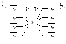
Schematic for two rings of coupled half cells, coupled
together through a single coupling resonator is illustrated in
Fig.4. This element represents a period of the four-beam accelerator
structure. The modes of resonantly coupled, multibeam structure
were analyzed by establishing the notation and normalization for
the simple structure so that the impedance matrix of the more
complicated multibeam structure can be written by inspection.

Since the internal modes don't propagate only if
the cells and coupling apertures are perfectly symmetrical, the
coupling factor k0 should be kept large to keep
the internal modes away from the operating frequency to reduce
the likelihood of coupling microwave energy to these modes.
Experimental Verification
Test resonator was made by combining the cells, shown
on Fig.5.

Coupling between the cavities in the rings was introduced
and changed during the measurements to study theoretical predictions,
which were in a good agreement with experimental results. We found
that the structure behaves like a conventional biperiodic structure
with multiple resonant frequencies which correspond to the case
of unexcited coupling cavity. Each of this frequencies represent
various modes for single "ring " of four resonators.
Detailed analysis of the experimental results was provided earlier
[2].
Four Beam 1.2 MeV Linac Head

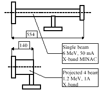
Length of FBS linac, which is approximately equal
to Lminac6 /4, where Lminac6 is,obviously,
length of MINAC-6. The latter is designed for energy of 6 MeV.
The improved version utilizes a shorter section and delivers 5
MeV electron beam with beam current of approximately 100 mA. As
RF length Lminac5 equals 40 cm, corresponding RF length
of a projected FBS approximately 10 cm.
Calculated and experimental load lines for MINAC-5
were in a very good agreement. The maximum current transported
through the section is 110 mA. This is a maximum value which we
were able to achieve in X-band linac using magnetron as a power
source.
If the proposed FBS linac would have similar characteristics
and four accelerated beams, simple considerations tell us that
using four times higher power magnetron (6 MW), beam current would
be 440 mA at the same energy of 6 MeV.
In FBS, we expect to increase beam efficiency to
about 60 to 70% and have 1 A at 1.2 MeV with the same magnetron
power (1.5 MW CTL1100).
Load line and efficiency for the proposed FBS is
shown on Fig. 7. Maximum energy is about 1.8 MeV, and efficiency
reaches its maximum at approximately 1.5 A beam current.
Beam dynamic analysis for the FBS short segment has
been made using PARMELA computer code. It shows that no focusing
is required for the electron beam in order to propagate down the
structure.

FBS was studied as an example of MBS concept, described
in [1,2]. The proposed technical study appears to be successful
and might help to solve the problem of beam current limitation
or increase energy gain by using mulripass operating mode. The
proposed concept seems to be a new technical approach in accelerator
structure construction and has a number of various practical realizations.
The concept could be used for e-beam processing, high energy radiography,
computer tomography, and other applications. It does not seem
possible to have every proposed design studied in details in a
reasonable period of time. However, we are hoping to continue
our study of various types of the proposed structure design. Potential
application of the proposed structure could be found in many areas
where accelerators are used.
This article concludes an analysis made during the
first stage of a study conducted in order to introduce the multibeams
structure design. We have proposed a "turn-key" prototype
linac using a miniature 12 cm long FBS and a 1.5 MW X-band magnetron
as a power source. Performance goal for the electron beam head
is to operate at beam energy of 1.2 MeV and beam peak current
of 1 A with no external focusing, providing, therefore, around
1 kW average power stored in four beams at 0.001 duty factor.
[1] A.V.Mishin, Multiple Beam Coupled Cavity Concept and Structure, Proceedings of EPAC96.
[2] H.Deruyter, A.V.Mishin, T.Roumbanis, R.Schonberg, R.Miller, J.Potter, Properties and Possible Applications of Multiple Beam Coupled Cavity Structure*, Proc.of EPAC96.
[3] J.F.Gittings, Power Travelling Wave Tubes, Amer.
Elsevier Publ.Comp., NewYork, 1965.