An important issue for the operation of a Linear
Collider with heavy beam loading is the temperature stability
of the accelerating structure. The phase and energy error is a
function of the temperature distribution on the surface of the
accelerating structure. Calculations prove, that keeping the temperature
constant at a specific point on constant gradient accelerating
structure minimises the energy error. This will be used for a
feedback system. The temperature at this point is a function of
the inlet water temperature, the average RF-power and the beam
loading.
An important issue for the operation of a Linear
Collider with heavy beam loading is the temperature stability
on the accelerating structure. The heat source is the difference
of the total input power and the power extracted by beam loading.
This difference can be calculated as the vector sum of the accelerating
voltage and the beam loading. The shunt impedance, the altennation
, the repetition rate and the pulse length are additional parameters.
The phase error itself is a function of the temperature distribution
calculated by this difference voltage. It is a function of the
wavelength, the group
velocity, the thermal expansion coefficient and the temperature
difference between the steady-state situation and the instantaneous
average temperature at every point on the surface [1].
The taper of the group velocity is linear and its
value at the inlet side is 4% and at the outlet side 1.3 % of
the velocity of light. The temperature rises almost linear, but
the temperature distribution on the surface is not.
In order to calculate this temperature distribution the following assumptions were made :
The following picture shows the average temperature
between the cooling tubes.

The temperature at the surface rises along the length
of the structure in absence of beam current. With increasing beam
current the power which is dissipated along the structure decreases.
Therefore the heat flow into the water is lower at the end of
the structure than at the beginning. This effect is more pronounced
with increasing beam current. Because the heat flow from the surface
to the water is a function of the temperature difference between
them, the surface temperature increases at first and then decreases
along the length with increasing currents.
The strong gradients on both ends are produced by
the heat flow into the tubes and in addition the return of the
water at the end.
The temperature distribution in a 3D-plot is shown
in the next picture. The beam current is 300 mA

The next picture shows the phase error caused by
the temperature distribution from figure 1. The temperature for
the steady-state system was arranged to be 40 0C with
a constant temperature at the inlet.

The integrated phase error turns into a beam energy
error along the structure length. This energy error on the other
hand can be minimised by changing the inlet water temperature
unless the integrated phase error is zero, which is always possible
because positive and negative phase deviations appear along zero.
Calculation shows that at a specific point the temperature remains
constant with varying beam or RF power, and varying inlet water
temperature for compensation.[2]

There are two layouts for the cooling circuit of the linac :
The first one is for the test-facility. The main demand for this cooling circuit was the high temperature stability over a large range of power deviations.[3]
The second is for the overall layout. The
main demand here was to have a simple cooling system with only
a few elements but flexible power handling capabilities
For the control of both systems the same elements
will be used :
the temperature is measured by a sensor at the specific
point, the temperature of the inlet water and the RF-power difference
between the input and output. The last one will be used for a
fast feedback system: with beam loading a definite input temperature
is required and therefore it is possible to change the inlet water
temperature before the surface temperature changes. The time available
to do this depends on the water flow and the heat capacity of
the structure and is about two seconds. Therefore in both systems
a hot and a cold line is required and the reqired temperature
is mixed by fast pneumatic mixing valves.
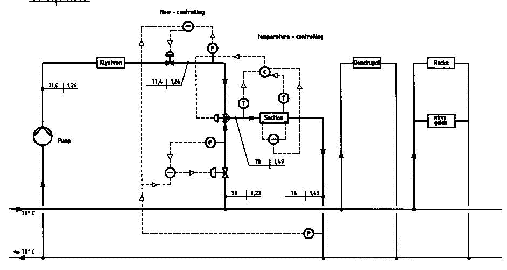
At the test-facility the solenoid of the klystron
is used as the main heat source for the hot line and for the power
reduction ( cool line ) a heat exanger. The rectangular
waveguides have a similar control system. The scheme is
presented in the next picture

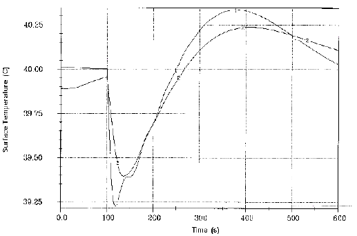
For this circuit a simulation [4] was made ( without
the feedback-system !): the power in the section and in the waveguide
was reduced by a factor of five ( this means e.g. changing the
repetition frequency from 50 Hz to 10 Hz ). The next picture shows
the result:

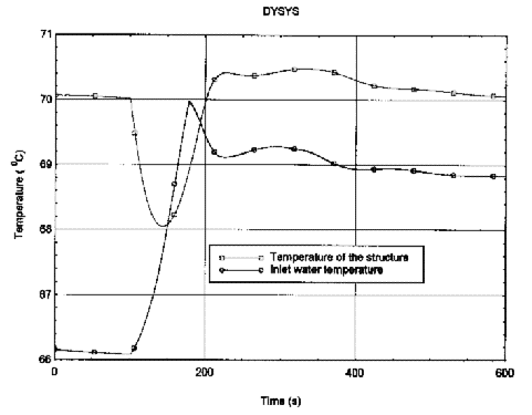
For the Linac Collider the klystron collector is used as a main heater source. It isn't possible to connect the heater with the supply water tube because the waterflow wouldn't be enough for cooling the section. Therefore it is connected with the return water tube and so a booster-pump is needed. The next picture shows such a possibility using only a few elements but on the other hand not applicable for a large range of power changes.

For this circuit a simulation was also made without the advantages of the feedback-sytem for the control. The next picture shows the inlet water temperature into the structure and the structure temperature when the power into the structure and klystron is reduced to a third of the previous value

[1] P. Lapostolle, A.Septier, 'Linear Accelerators Accelerating Structures Technology ', North Holland Publishing Company, Amsterdam 1980
[2] J. Hamsom, 'High duty factor electron linac'
[3] J.G. Noomen, N.Geuzebrouk, C. Schiebaan, ' A modular cooling system for the MEA high duty factor electron linac, IEEE Transactions on Nuclear Science, Vol NS - 28, No 3
[4] Frank-R. Ullrich, 'Leistungsrampen des PETRA-Ringes' , MKK-Aktennotiz 24/91 , DESY Internal Report