* on leave from IHEP
100039 Beijing, China
The S-Band linear collider testfacility at DESY serves as a testbed for components which will be necessary to build an S-Band linear collider. The testfacility requires two S-Band klystrons operating at 2.998GHz, each producing an output power of 150MW at a pulse duration of 3µs and a repetition rate of 50Hz. The high voltage pulses for the klystrons will be supplied by two line type modulators, which produce pulses of up to 535kV at currents of 700A with a flat top duration of 3µs and a repetition rate of 50Hz. The first klystron-modulator system has been installed and was commissioned at the S-Band testfacility at DESY.
This paper describes the layout and
the hardware of the klystron-modulator system. The results of
the commissioning of the first system will be presented.
Two of the main issues for future linear colliders are klystrons and modulators. They represent one of the major contributions to the total cost of a linear collider and determine to a major part besides other things its reliability and stability. Therefore klystrons and modulators are among the research objects at all linear collider testfacilities around the world.
The S-Band linear collider testfacility under construction at DESY is a 400MeV electron linac with four 6m long accelerating structures [1]. In order to achieve the loaded accelerating gradient of 17MV/m it requires two klystrons operating at 2.998 GHz at an output power of 150MW. In 1993 a collaboration between SLAC, DESY and Philips started to develop and build two 150MW klystrons which could be used at the S-Band testfacility. Two klystrons have been built at SLAC and shipped to DESY until 1995 [2]. A line type modulator has been constructed to test the 150MW klystrons at SLAC [3]. In parallel DESY started to build two line type modulators for the operation of the klystrons at the S-Band testfacility. Therefore both modulators, the SLAC and the DESY modulator, have a very similar PFN unit and pulse transformer tank.
Although it is necessary to investigate alternative techniques for high voltage modulators for future linear colliders, the well established technique of the line type modulator has been chosen for the modulators at the S-Band testfacility. The first reason was, that line type modulators represent the most advanced method to produce high voltage pulses at this power level. The second reason for choosing line type modulators was, that they are of course one possible choice for the generation of pulsed high voltage for the klystrons of a linear collider. Therefore they are still one object of investigation and research. Alternative techniques are also under investigation at DESY in addition [4].
This paper describes the first 375MW line type modulator at the
S-Band testfacility at DESY, the requirements, the circuit and
the hardware. Results of the commissioning are reported.
Two 150MW klystrons have been developed and built at SLAC. Table 1 shows the design goals and the achieved parameters of the two klystrons.
| Design | Tube#1 | Tube#2 | |
| Power Out | 150 MW | 153 MW | 150 MW |
| Pulse Duration | 3 µs | 3 µs | 3 µs |
| Repetition Rate | 60 Hz | 60Hz | 60Hz |
| Beam Voltage | 535 kV | 527 kV | 508 kV |
| Beam Current | 700 A | 680 A | 652 A |
| Microperveance | 1.79 | 1.78 | 1.80 |
| Efficiency | 40 % | 43 % | 45 % |
| Gain | > 50 dB | 56 dB | 57 dB |
The klystrons require a solenoid, which
is made of three independent coils. Two of them are supplied by
one common power supply, whereas the third coil around the output
cavity is controlled independently by another supply. Typical
currents are 42A at 285V and 35A at 45V. In order to achieve zero
magnetic field on the klystron cathode a bucking coil is needed.
It typically runs at 3A and 4V. The parameters in Table 1, especially
the beam voltage and current and the RF pulse duration, determine
the modulator requirements. The required repetition rate at DESY
is only 50Hz.
The modulator consists of four separate big components, the PFN unit with the pulse transformer tank, the charging unit (CHU), the HV power supply and a control unit. The basic parameters of the modulator are shown in Table 2. The electrical circuit can be seen in Fig. 1.
| Pulse Voltage | 535 kV |
| Pulse Current | 700 A |
| Flat Top Pulse Duration | 3 µs |
| Repetition Rate | 50 Hz |
| Equivalent Square Wave Duration | 4.8 µs |
| Rise Time 10 - 90 % | 700 ns |
| PFN | four lines parallel, each line ten sections |
| PFN impedance | 1.34 |
| Total Capacitance | 1.8 µF |
| Capacitor Capacitance | 45 nF |
| Coil Inductance | 1.3 µH |
| Charging Voltage | 50 kV max. |
| Peak Current (primary side) | 16 kA |
| Pulse Transformer Ratio | 1 : 23 |
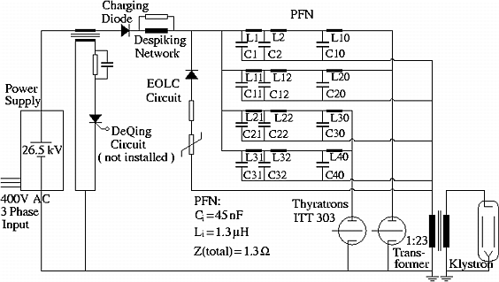
Fig. 1. Schematic Drawing
of the Electrical Circuit
The cabinet of the PFN unit is 1.4 *
1.5m wide and 2.6m high. All components in the cabinet are under
air. Each of the four PFN lines consists of 10 capacitors and
10 coils (see Fig. 1). The capacitors (CSI, San Diego, USA) have
a capacitance of Ci=45nF
and a voltage rating of 50kV. They are mounted horizontally and
connected with one side to an aluminum rack. One copper coil is
fastened on top of each capacitor. The inductance is adjustable
by changing the tap on the coil and by changing the position of
a slug inside the coil. The nominal inductance of one coil is
Li=1.3µH.
The equivalent square wave pulse duration of the PFN calculated
by T=2N(LiCi)1/2
is 4.8µs (N is the number of sections per PFN). The nominal
impedance of the PFN is 1.34![]() .
The total capacitance is 1.8µF,
which gives a stored energy of 2.25kJ at 50kV. In order to protect
the klystron in case of arcing an End of Line Clipper (EOLC) is
installed in the PFN. It consists of six 20
.
The total capacitance is 1.8µF,
which gives a stored energy of 2.25kJ at 50kV. In order to protect
the klystron in case of arcing an End of Line Clipper (EOLC) is
installed in the PFN. It consists of six 20![]() resistors in parallel, a varistor and a diode
stack with 28 high voltage diodes in series and varistors in parallel.
The mounting rack is connected by a copper line and a feed through
to a 1:23 pulse transformer (Stangenes, Palo Alto, USA) in the
transformer tank. Two thyratrons (ITT F-303) are installed
in the cabinet. The anode side of the thyratrons is connected
to a thyratron mounting rack, which is attached to the other copper
stripe of the feed through. This copper stripe serves as current
return pass from the pulse transformer. A fast voltage divider
(30ns risetime) is connected to the capacitor mounting rack. This
allows to measure the primary pulse voltage.
resistors in parallel, a varistor and a diode
stack with 28 high voltage diodes in series and varistors in parallel.
The mounting rack is connected by a copper line and a feed through
to a 1:23 pulse transformer (Stangenes, Palo Alto, USA) in the
transformer tank. Two thyratrons (ITT F-303) are installed
in the cabinet. The anode side of the thyratrons is connected
to a thyratron mounting rack, which is attached to the other copper
stripe of the feed through. This copper stripe serves as current
return pass from the pulse transformer. A fast voltage divider
(30ns risetime) is connected to the capacitor mounting rack. This
allows to measure the primary pulse voltage.
Directly connected to the PFN unit is
the oil filled pulse transformer tank. It has a diameter of 1.3m
and a height of 1.6m. The klystron with its solenoid sits on top
of the tank with the klystron gun ceramics in the oil. The design
klystron resistance at full power is 764![]() ,
which together with the step up ratio of the
transformer of 1:23 represents a load impedance of 1.44
,
which together with the step up ratio of the
transformer of 1:23 represents a load impedance of 1.44![]() to the PFN. A
1:10000 capacitive voltage divider is connected to the secondary
side. A Pearson current monitor allows to measure the gun current.
The filament transformer and the blocking coil for the core bias
power supply are also installed inside the tank. The interior
of the PFN unit is shown in Fig. 2.
to the PFN. A
1:10000 capacitive voltage divider is connected to the secondary
side. A Pearson current monitor allows to measure the gun current.
The filament transformer and the blocking coil for the core bias
power supply are also installed inside the tank. The interior
of the PFN unit is shown in Fig. 2.
Fig. 2. Interior of the PFN
Unit
The PFN unit is connected to the charging
unit (CHU) by a HV cable. The CHU cabinet is 1.35 * 1.45m wide
and 2.45m high. Inside the cabinet one can find the charging choke
(Kirchner, Hamburg, Germany) with an inductance of 16H. This inductance
together with the total PFN capacitance of 1.8µF gives a
charging time of 17ms. The maximum charging current is 9A. 36
high voltage diodes, two times 18 parallel diodes in series, serve
as charging diode. A despiking network made of chokes and resistors
is connected to the cable to the PFN. The charging choke has a
secondary winding. This allows to install a deQing circuit in
the charging unit, if better pulse to pulse regulation of the
charging voltage might be necessary.
The HV power supply is a commercial
power supply (Heinzinger, Rosenheim, Germany) with the dimensions
1.4 * 1.85m wide, 2.25m high. It has an output voltage of 26.5kV
max. at a maximum average current of 5A. The supply has an SCR
controller, which leads to a stability of the voltage better than
1%. The power supply can be controlled locally or remotely via
a GPIB interface.
All the controls are installed in four
19" racks of 2m height. The modulator can be operated locally
from this unit. Inside the racks one can find the heater supplies
for the thyratrons and the klystron, the vacion and bucking coil
power supplies, the control unit for the core bias power supply,
scopes, trigger generators, monitors and printers. One 19"
rack is reserved for a programmable logic controller (Siemens
S5-135U). All technical components of the klystron and the modulator
are interlocked by the PLC. In addition temperatures, flows and
pressures are recorded by the PLC. The PLC is connected to a SUN
workstation via profibus, which will make it possible to operate
the modulator remotely from the SUN workstation. The cycle time
of the PLC program is less than 20ms. In case one component fails
the modulator could be shut off pulse to pulse. The additional
personal interlock is made by a relay unit.
The first tests of the klystron and modulator were done without applying drive power to the klystron. Operation started at a low repetition rate of 10Hz and short pulse width. For this purpose five capacitors per PFN line were removed. This resulted in half of the full pulse width. The klystron was brought up to more than 500kV without problems. After it drive power was applied to the klystron. Two waterloads, each capable of 75MW, had been installed on the two output waveguides of the klystron. It took in the order of two hundred hours to improve the vacuum conditions in the waveguide of the waterloads before 150MW at 1.2µs and 50Hz repetition rate were achieved. The maximum beam voltage was 550kV at 700A. After it all capacitors were installed. Conditioning started again with low repetition rate, but full pulse width. As oscillations had been observed in klystron #1 at certain voltage levels and magnetic field settings during testing at SLAC, commissioning at full pulse duration needed to be done very carefully. It is necessary to adjust the magnetic field very carefully each time one increases the beam voltage. In addition the vacuum conditions in waterloads limited the speed of conditioning. Almost 150MW at 3µs have been reached. Fig. 3 shows typical waveforms at this level. The 10 to 90% rise time is 700ns and the flat top duration 3µs as required. Up to now no efforts have been made to improve the flatness of the pulse top. This will be done in the next step by adjusting the inductance of the PFN coils.
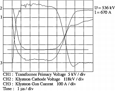
Fig. 3. Typical Waveforms
at 536 kV and full Pulsewidth
It is planed for the next steps to bring the klystron up to full power at 50Hz repetition rate and to smooth the pulse top. The remote control of the system will be tested in addition. After it the waterloads will be removed and an accelerating structure will be installed and conditioned.
A second modulator is under construction.
It is planed to start with the operation of the second system
at the beginning of next year.
The authors would like to acknowledge
the support of S. Gold and D. Sprehn of SLAC. Thanks for many
helpful discussions.
[1] R. Brinkmann, "Low Frequency Linear Colliders", Proc. of the Fourth European Particle Accelerator Conf., EPAC94, p363, London(1994)
[2] D. Sprehn, R. M. Phillips, G. Caryotakis, "Performance of a 150-MW S-Band Klystron", AIP Conference Proceedings 337, Pulsed RF Sources for Linear Colliders, p43, Montauk (1994)
[3] R. F. Koontz, S. Gold, J. Eichner, "Recent Performance of Klystron Testing in the SLAC Klystron Test Lab", Proceedings of the 1994 International Linac Conference, p445, Tsukuba (1994)
[4] M. Bieler, S. Choroba, J. Hameister, H.-Ch. Lewin, R. Giebeler, S. Gold, "Commissioning of the Hard Tube Pulser Experiment at DESY", Proceedings of the Fourth European Particle Accelerator Conference, EPAC94, p1933, London(1994)