The 200 MeV linac at BNL has recently been upgraded.
As a result, 2.5 times more average beam current can be delivered
to the Brookhaven Isotope Resource Center (BIRC), formerly called
BLIP, a facility which produces radionuclides and radiopharmaceuticals
for the medical community, and also supports a research program
seeking more effective diagnostic and therapeutic agents. The
optics of the beam transport line to BIRC was redesigned to (a)
reduce transverse fluctuations of the beam at the target due to
any linac energy fluctuations, (b) produce a flat beam distribution
at the target, in order to avoid melting certain target materials,
and (c) handle the higher beam intensity while keeping radiation
levels low. A profile monitor was also modified to monitor the
flatness of the beam using the algebraic reconstruction technique
(ART). The above improvements will be described, and results of
the commissioning of the line during the 1996 running period will
be discussed.
The recent upgrade of the 200 MeV linac, reported in these proceedings[1], has resulted in a 150% increase in the average beam current that can be delivered to the BIRC facility, which is the largest consumer of the linac's pulses. The optics of the transfer line was redesigned in order to keep radiation levels within acceptable levels and to produce a flat, rectangular beam at the target location, in order to avoid melting certain target materials. The redesign also included making the two bends in the transfer line achromatic, as well as the addition of a third wire to an existing secondary emission monitor (SEM) to make possible a 3-D reconstruction of the beam profile using ART, also reported in these proceedings[2].
The constraints of the exercise were that the existing physical layout of the line would be retained, and existing equipment in the line and/or available equipment at the AGS, would be used whenever possible.
Most of the design effort went into producing a beam
with a flat intensity distribution and rectangular cross-section
at the BIRC target, and the rest of this paper will deal exclusively
with this aspect of the project. Achromaticity of the two bends
was provided for by mounting a second quadrupole between the bending
magnets, while keeping the beam size small wherever possible minimized
radiation levels.
Beam flattening exploits the aberrations introduced by non-linear lenses. In principle, any non-linear focusing elements, i.e., those for which the restoring force on the beam particles rn, where n =3, 5, 7…, will do. In practice, octupoles, n=3, are generally used. The principle of the method is to manipulate the beam envelopes in such a way that, at two suitable locations, the beam envelope is small (large) in one plane, and large (small) in the other. The octupole magnets are placed at these locations, and their strengths adjusted to give the required beam properties at the target. (This arrangement of having the beam small in one plane and large in the other at the octupoles, minimizes the horizontal/vertical coupling and makes tuning the octupoles easier; it also results in a rectangular cross section at the target.) The appropriate beam correlation coefficient, C12 or C34, at each octupole in the plane where the beam is large should also be very close to unity, in order that the intensity distribution at the target falls off sharply.
Experimental confirmation of this approach was obtained at BNL's Radiation Effects Facility[3].
A schematic layout of the new BIRC line is shown
in Fig. 1. Total length of the line is 33.5 m.

The following programs were used for the study: TRANSPORT[4], TURTLE[5], TRACE3D[6], and NSC[7]. TRANSPORT was used to find the first-order beam parameters required for flattening while determining possible locations of the octupoles. NSC, similar to TURTLE, was used to find the octupole strengths which gave the desired beam properties on the target. TURTLE repeated the third order calculations, but provided information to reconstruct the third-order beam envelopes in a straightforward manner. TURTLE, and TRACE3D were used to examine the sensitivity of the final design to misalignments and magnet imperfections, in particular, the (sub)harmonics of the octupole magnets.
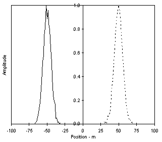
Fig. 2 shows the design beam envelopes for flattening.
The phase space plots and profiles are in Fig. 3.
Commissioning was parasitic to other BIRC activities,
hence it proceeded very slowly. The activation method of measuring
beam profiles at the target location has a turn- around time of
several hours at best, and several days at worst, thus making
it impossible to tune the beam on target while monitoring it on
a pulse-to-pulse basis. As a result, most of our studies concentrated
exclusively on the multiwire profiles. (A 3 m drift separates
the last profile monitor and the target.)


Diagnostic Equipment
Equipment used included: multiwire harps at locations REFMW and BIRCMW in Fig. 1, to provide horizontal and vertical beam profiles; a 3-wire SEM at SEM3 which provides data for 3-D reconstruction of the beam intensity profile using ART; a system for exposing aluminum targets to the beam and measuring their activity profiles as a means of obtaining the 3-D beam profiles at the target. SEMs immediately after the Linac were used for emittance measurements, while radiation monitors along the beamline showed when and where beam was hitting the beam pipe.
The data collected consisted of the quadrupole and
octupole currents, and the multiwire and irradiated target profiles.
Beam emittance was measured infrequently.
Data Analysis
The magnet currents were converted to fields using
measured, and for the last three quads, calculated characteristic
curves. The fields were then used in the computer model of the
line to obtain beam envelopes, and 2-D and 3-D profiles, which
were compared to those measured.
We mentioned earlier that most of our effort to understand
the optics of the line was concentrated on beam profiles at REFMW
and BIRCMW. The latter is of more interest because it is after
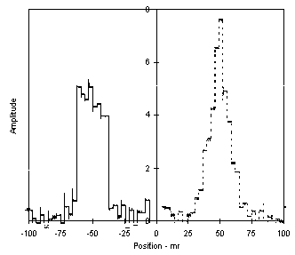
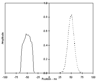
the octupoles. Figs. 4 and 5 show observed and calculated beam
profiles for a tune which produced a flat vertical profile and
another tune with the octupoles off. The agreement between observation
and theory(TURTLE) is excellent. The widths and relative heights
of the measured and calculated profiles agree very well.
The objective of a flat rectangular beam on the BIRC target needs more work to be fully realized. Progress has been slow due mainly to the slow feedback from profile measurements at the target and the absence of measured characteristics of the last three 6 in. aperture quads. Three-dimensional modelling of the quads has recently been used, first as a test on the original 4 in. aperture magnets, and then on the modified 6 in. aperture quads. It gave reasonably accurate characteristics which were used in the TURTLE model. (Radiation levels permitting, one of the quads may be removed for bench measurements during the present shutdown.) Work continues on finding a better and faster way to measure the profiles at the target.
We now know that the difficulty in flattening the
beam horizontally was due to the smaller horizontal beam envelope
and lower correlation, C12, at the first octupole. In the initial
stages of commissioning, the line was retuned for a smaller envelope
upstream of the second bending magnet because of high radiation
losses. A first-order tune will be found to address this problem.


We acknowledge the very valuable and continuing contributions
of Leonard Mausner and his team at BIRC, Brian Briscoe at the
Linac, Dave Schlyer of the Chemistry Department for the activation
measurements, and the staff of SIGMAPHI (France) for meeting our
very tight schedule for manufacture and delivery of the octupole
magnets.
1. J. G. Alessi et al.," Upgrade Of The Brookhaven 200 MeV Linac," Proceedings of this Conference.
2. D. Raparia et al., "Comparisons Between Modeling and Measured Performance Of The BNL Linac," Proceedings of this Conference.
3. N. Tsoupas et al., Proc. IEEE Particle Accelerator Confernce, San Francisco, 1991, p. 1695.
4. K.L. Brown, D.C. Carey, Ch. Iselin and F. Rothacker, CERN Report No. 80-04 (1980).
5. C.D. Carey, FNAL Report No. NAL-64 (1971).
6. K. R. Crandall, Revised by D. P. Rusthoi, TRACE 3-D Documentation, LA-UR-90-4146.
7. N. Tsoupas, private communication. (The significance
of the letters NSC has long since been lost.)