Precisely controlled frequency distributions of the
higher modes in each cell and the good straightness of the cells
along the structure are the key issues on the detuned structure
for the main linac of the Japan Linear Collider. The fabrication
studies of a few full-size accelerating structures have been performed
based on the technique of the ultra-precise machining of the cells
and the diffusion bonding to join them. As of today, the frequency
controllability of each cell was found to be better than 1Mhz
in the standard deviation of the accelerating mode and the alignment
of the cells along the structure was found to be better than 10
mm.
The preservation of the multi-bunch emittance is one of the key issues to reach a required high luminosity for the most of the present-day linear colliders[1]. One of the source of the emittance growth is the dipole wake field due to the accelerating structure. Three methods have been proposed so far, heavily damping, detuning with a medium damping and purely detuning. In the present paper was studied the last approach, "purely detuned structure".
In order to realize this approach, the control of the frequency distribution of the dipole modes and the transverse positions of those modes with respect to the beam is essential to realize the designed cancellation of the wake field. In the Japan Linear Collider, JLC[1], each structure consists of 150 cells and four structues are interleaved in dipole mode frequency. In this case, the frequency spacing between nearest neighbor is about 1Mhz. Because the stored energy of most of the modes are spreading in more than 20 cells, it is enough to control the random error in each cell frequency better than 1Mhz. The tolerance of the alignment of those modes along the structure is assumed as 5 mm from the simulation results for NLC[2], where most of the parameters are similar to those of the JLC.
To meet the tight tolerance of the frequency control, the cells which consist of the structure are firstly machined with an ultra-presise lathe and a milling machine. Secondly they are bonded through a diffusion process between the flat surfaces of the cells. No tuning is performed after bonding.
From the previous fabrication studies of 30cm-long
constant-impedance structures, the bonding at a temperature above
800_C was found reliable to obtain the vacuum tight junction for
the present quality of the machined cells[3]. The change of the
accelerating mode frequency is less than 1MHz out of 11.4GHz.
It is necessary to study the applicability of the present fabrication
technique to the 1.3m detuned structure.
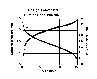
In order to make the detuning of the dipole modes, the beam hole radius and the disk thickness are varied so that the unperturved dipole modes are distributed in a truncated Gaussian. The actual parameters are shown in Fig. 1. The cell inner radius "b" was determined to make the 2p/3 mode to be the operating frequency. Practically, the frequencies at three points along the structure were studied experimentally by measuring the frequencies of the resonant 2p/3 modes in varied number of regular cells with half end cells at both ends to estimate the frequencies in the periodic structure. Using these three points as a correction to the precise numerical estimation of the frequencies at the other points in the structure, all the dimensions "b" were determined[4].
Three 1.3m structures were fabricated. The first one, called "M1", came out with severe vacuum leakage after the first diffusion bonding at 800_C. We speculate that this failure is largely due to the complex shape of the cells where four slots are sitting on the bonding surface so that there might be many burrs which make the reliable bonding difficult. In the follolwing two structures, "M2" and "IH1", the slots on the bonding surface were removed. The rather large diameter of 80mm is for stabilizing the stacking and bonding processes in addition to integrate the water cooling channels to make the fabrication as simple as possible for mass production purpose. The coupler cells are firstly milled to make the two symmetrical wave guide ports with a precision of 1 mm and then the cell inner surface and bonding surface are cut by the ultra-precise lathe. In Table 1 are listed various fabrication informations of the two structures.
All the cells are machined using a ulrtra-precise
lathe to make the bonding surface to be as flat as possible, typically
0.3 mm or
better, with a surface roughness of 50nm. These cells were chemically
rinsed in a series of weak acid, pure water and acetone bath.
The cells are stacked along a Vee block and compressed in the
axial direction. Keeping the compression force and hanging vertically
in a vacuum furnace, the stack is diffusion bonded to join all
the important part of the structure. The symmetrical wave guide
ports, which are coated with 10 mm
thickness of silver were brazed in the next furnace operation
with a wire brazing alloy as a backup.
| Structure | M2 | IH1 | |
| temperature | _C | 850 | 890 |
| period | hours | 4 | 0.2 |
| pressure at top | kg | 16 | 40 |
| stacking | hor. V | ver. V | |
| furnace | vacuum | vacuum |
The first step to realize the good frequency control is of course to cut the cells in a good precision. In the case of M2, the standard deviation s of 2b is 0.41mm while maximum deviation is +-2s, which is precise enough to satisfy the tolerance of 1Mhz.
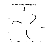
To check the frequency change due to the bonding process, the reflection phase seeing from the input wave guide were measured by shifting the plunger of 5mm in diameter inserting from the output coupler side. This nodal shift measurement were performed just after stacking and just after bonding. An example is shown in Fig. 2. The plunger was moved in 0.2mm step and the dwelling points were deduced by finding the point of a minimum movement in the reflection phase. Due to the large difference of diameter between the plunger and the beam hole, especially near the input side, the dwelling points were shifted by more than 0.5mm from a nominal position along the structure. This behavior appeared in the reflection phase shifting from a simple line of 240_/cell near the input coupler.
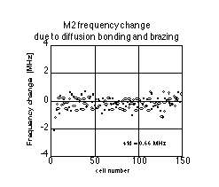
From the nodal shift measurement, the phase difference due to the movement of the plunger through three cells were used to estimate the frequency shift of the cells. This analysis removes such effects as the mismatch at the input and becomes more precise than the direct comparison of those between the adjacent cells. In Fig. 3 are plotted the frequency changes due to the whole bonding processes of M2. The standard deviation s of the frequency change was found 0.66Mhz while almost all the cells are within +-1.5s. It is to be noted that the standard deviation of the frequency change in the first diffusion bonding of IH1 case was as large as 1.1Mhz while that through the additional diffusion bonding and the final brazing only 0.4Mhz. The larger value in the first bonding than that of M2 case might be due to the poor surface flatness or a higher temperature of bonding comparing to the M2 case. The frequency shift in M2 is tolerable but the characteristics of the frequency change on the bonding parameters should be studied further.
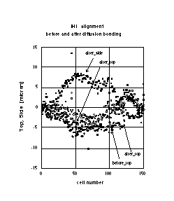
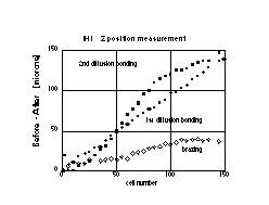
The cell alignment was measured just after stacking
the cells but before removing from the vee block. The measurement
was performed by capacitive sensor, microsense. In Fig. 4 are
shown the case of IH1. The cells were found to follow the vee
block within 8mm
by a simple stacking in a horizontal vee. Because of the miscut
of some of the cells in their outer diameter, OD, the alignment
data were corrected by using measured OD's. Some data points which
deviate much from the smooth line are speculated to be due to
the mismeasure of the OD of the particular cell. The alignment
change due to the bonding was found less than 10mm.
A similar characteristics but a little worse alignment of the
order of 20 mm
was found in the case of M2 than that of IH1. It should be noted
that the cell to cell movement was very small in M2 case, where
almost 1 mm.
There are a few different points between the fabrication process
of IH1 and M2, such as vertical stacking or horizontal, and there
is a room to further study and refine the alignment of the cells
to meet the required tolerance of several mm
reliably.
In order to proceed the plastic deformation to fill the gap between the cells during the diffusion bonding process, the pressure was applied ranging from 3 to 20g/mm2. Rather long period of diffusion bonding process under this pressure at high temperature makes the cells shrink. In Fig. 5 is shown the case of IH1. The measurement was performed by measuring the distanse from the end of the structure to the cell position. The shrinkages of both first and second diffusion bonding at 890_C were about 1mm per cell. That of the final brazing at 800_C was found only 0.3mm. The shrinkage was found 0.87 mm in the M2 through a diffusion process and a final brazing in total.
Three structures were fabricated to study the precise fabrication method of 1.3m accelerating structure. The last two structures came out to be vacuum tight and various characteristics were discussed.
The accelerating-mode frequency of each cell can be controlled with the standard deviation of 0.41Mhz in cell machining while that due to bonding 0.66Mhz. The relative frequency error of the TM110 mode is estimated to be almost the same as that of the accelerating mode. Therefore, the standard deviatin of the random frequency error of the TM110 mode in each cell is about 1Mhz.
The alignment of the cells along the structure were
better than 10 mm.
The present simple stacking method should be refined to make the
alignment better by a factor of 2. Each cells were found to be
shrinked by about 1mm.
The authors would like to thank Dr. S. Koizumi for
encouraging us continuously on the ultra-fine machining activities
at KEK machining center. Many experimental studies, especially
the furnace-related operations were performed in the collaborative
activities with Ishikawajima-Harima Heavy Industry and Mitsubishi
Heavy Industry. They are greatly acknowledged.
[1] G. A. Loew and T. Weiland ed., "International Linear Collider Technical Review Committee Report"
[2] "Zeroth-order Design Report for the Next Linear Collider", LBNL-PUB-5254, SLAC Report 474, UCRL-ID-124161, 1996.
[3] T. Higo et al., "Precise fabrication of X-band Detuned Accelerating Structure for Linear Collider", Proc. 1995 Part. Accel. Conf., Dallas, p1753 (1995), and KEK Preprint 95-22(1995).
[4] T. Higo et al., "practical
application of very precise frequency calculation to a disk-loaded
structure", in Japanese, Proc. 20th Linear Accelerator Meeting
in Japan, Osaka, Japan, 1995.