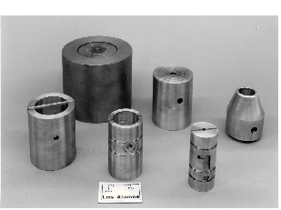
Thermal management, resonance control, and reliability requirements become predominant when designing "conventional" copper coupled-cavity linac (CCL) structures for very high duty factors and accelerating fields. Whereas the outer body of the coupled-cavity drift-tube linac (CCDTL) is in most ways comparable to the CCL, the cooling and support of the added drift tubes present totally new and interesting challenges. Making provisions to limit thermal distortion calls for many cooling passages, high quality materials, and new fabrication schemes and techniques.
Thermal designs for a 700MHz linac are presented,
along with results of prototype tests and fabrication developments
which offer solutions to all of these problems.
Active mechanical elements, such as movable slug tuners, are used to regulate the resonant frequencies of many existing room-temperature copper accelerating structures. Many others are regulated by modulating the structure temperature. (Increasing the average temperature of a room-temperature copper structure by 1°C causes it to expand approximately 1.8e-5:1 in all directions unless it is constrained somehow. Uniform thermal expansion lowers the resonant frequency of the rf structure proportionately.) Resonant frequency control via temperature modulation is the better choice for high-power rf structures since they require active, closed-loop temperature control anyway, and since mechanical tuning elements add significant cooling problems of their own.
However, because cooling cannot be perfectly distributed,
temperatures are, in general, not perfectly uniform, giving rise
to local thermal distortions. These distortions can greatly effect
the resonant frequency and field distribution in the accelerating
structure, even when the "average" structure temperature
is "right". This paper explores the sensitivity of various
types of rf cavities to distortions, and discusses means for controlling
these distortions appropriately.
A common "room-temperature" accelerating structure is the coupled-cavity linac (CCL, also sometimes called a side-coupled linac, or SCL). Typically, the CCL structure consists of several of these cavities in series, as shown in Figure 1. For low-power applications (low accelerating fields, or low duty factor), coolant passages incorporated into the outer cylindrical walls are often sufficient. For high-power application, the end and internal walls and drift tube noses must be actively cooled to prevent marked steady-state frequency errors, and, in some cases, permanent plastic deformation during rf transients.

The fabrication scheme shown in Figure 1 provides an easy means for incorporating many integral coolant passages. Interconnected rectangular grooves are cut into the flat interfacing surfaces of the various pieces that make up the stacked assembly. Typically, these interfaces are hydrogen-furnace brazed using copper/gold or copper/silver alloys to form a quasi-monolithic structure. In a high-power application, it is virtually impossible to avoid having some water-to-vacuum braze joints. Although several laboratories remain adamantly opposed to such joints, at LANL, we have had no significant problem with water-to-vacuum leaks in copper-to-copper braze joints.
Current LANL linac design standards limit the coolant water velocity inside these enclosed passages to about five meters per second. This is much higher than recommended in commercial copper piping. Nonetheless, many OFE copper linacs have been built and operated for many years with velocities in this range. (Two recent failures have occurred in the Alvarez Drift Tube Linac portion of the 25+ year-old LANSCE accelerator, where local water velocities over 6.5m/s caused erosion through thin-walled copper parts, but near-by braze joints were not effected [1].) Avoiding sharp bends and sudden cross-section changes in the vicinity of thin walls is recommended.
The 700MHz CCL segment shown in Figure 2 is for particle = 0.86, where is the ratio of particle velocity to the speed of light. Its thermal distortion is shown, exaggerated by 2000X, corresponding to the cooling design planned for the APT room temperature linac. For the following discussion, consider the structure broken into three zones, the outer cylindrical body, the end walls and noses, and the internal walls and noses.

Obviously, when the outer cylindrical body gets hot, it expands outward, increasing the electrical inductance of the cavities, and thereby lowering the resonant frequency. Less obvious is its structural interaction with the end walls, described later.
Typically, there are several cavities in series, so most of the walls are internal, with equal rf heating on both sides. As the noses get hot, they grow too long, closing the accelerating gaps somewhat, and they expand radially. Both of these components act to increase the electrical capacitance of the cavities, lowering the resonant frequency. The wall itself is loaded symmetrically, so its principal movement is radially outward, pushing part of the cylindrical outer body ahead of it. This increases the electrical inductance somewhat, which also lowers the cavity frequency.
The end walls are generally thicker than the internal walls because they must react vacuum loads. Their thermal distortion is less well behaved because the thermal loading is one-sided. A simple disk, heated on one side and cooled on the other would deform into a dish shape, convex on the heated side. However, the end wall is rigidly attached at its perimeter to the outer cylindrical body. If the end wall is hotter than the outer cylindrical body, the mismatch causes the end wall to bow outward rather than inward. This greatly increases the cavity's electrical inductance. It also increases the length of the accelerating gap of this end cavity. This latter effect is offset somewhat by the lengthening of the nose and its radial expansion. The net effect is still to lower the frequency of the end cavity. If the end wall is cooler than the body, it is bowed inward, with equally mixed effects. Thicker end walls bow less, and behave more like internal walls.
In this high-beta example, the end wall and internal
wall temperatures have about equal influence on the resonant frequency
of individual cavities. At lower , the end wall can have a much
greater effect than an internal wall. This is mostly because the
nose-to-nose gaps are shorter, so small end wall displacements
are large in proportion. Also the noses themselves are shorter,
and less of a factor in the structural interplay. Nevertheless,
because there are so many internal walls and only two end walls
in a typical CCL accelerating segment, the "average"
resonant frequency of the segment is not strongly effected by
the end wall and nose temperatures.
The CCDTL accelerating structure has been proposed for use on high-current, intermediate velocity beams [2]. In the 700MHz APT linac, it appears in three forms [3,4]. For =.12-.13, two-gap cavities, one cavity per segment are used. (ref. [2].) For =.13-.20, individual three-gap cavities are used (left side of Fig. 3). For =.20-.43, two-gap cavities, two cavities per segment are used (right side of Fig. 3).

The outer bodies, end walls and internal walls of CCDTL structures are made and behave exactly like those of the CCL structure described earlier. However, because there are only one or two cavities per accelerating segment, the end wall behavior can have a surprising and significant frequency effect.

Figure 4 shows an exaggerated shape for a =0.2 segment whose end walls have been artificially heated 2.8C (5F) above their normal operating conditions. As expected, it has bowed outward. However, because the initial gaps are small, the gap increase is relatively quite large. Although the inductance increase is significant, it is not enough to compensate for this big capacitance drop. The net effect is a substantial increase in the cavity frequency.
The =0.43 segment, shown in Figure 5, has larger initial gaps. The capacitance and inductance factors almost exactly cancel, making resonant frequency independent of end wall temperature!

In CCDTL cavities, a large fraction of the rf loss occurs on the drift tubes, and their thermal distortion has a very marked effect on the resonant frequency of all of these cavities. In the 700MHz =.43 cavity, heating the drift tube 5C causes the resonant frequency to decrease 29kHz, while uniform heating of the outer body and wall causes a 34kHz decrease. Most of the drift tube's frequency/temperature dependence resides at its noses, nearest the accelerating gaps. Analysis shows that artificially heating only the drift tube noses by 5C lowers the cavity frequency 25.7kHz. As the noses get longer and larger in diameter, the gaps get shorter and the surface area increases, increasing electrical capacitance, and thereby lowering the cavity frequency. In contrast, heating the middle portion of the drift tube has very little effect on the cavity resonant frequency. Although the middle portion growth shortens the accelerating gaps, increasing electrical capacitance, it also moves outward into the high magnetic field region, decreasing electrical inductance. In the =0.43 case, the frequency effects almost exactly cancel.


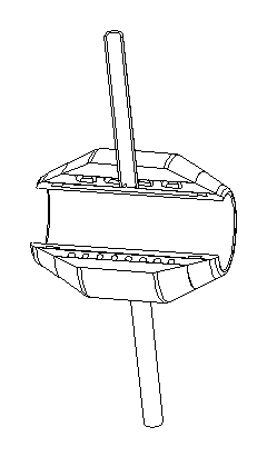
Thus, cooling the drift tube noses becomes very critical. Getting coolant to the noses is not easy. Several schemes were analyzed and rejected before the construction shown in Figure 6 was developed. Three copper cylinders are made with approximately 75microns radial clearance when assembled. Coolant passage grooves were lathe-cut into the outer surface of the two inner copper cylinders, and then interconnected with milled slots on alternating sides. 50micron Cu/Au alloy foil is inserted between the cylinders, and the entire assembly is surrounded with a molybdenum TZM ring and an appropriate amount of 304 stainless steel shim. When the assembly reaches braze temperature, the copper has expanded much more than the molybdenum sleeve which forces the soft copper to compress onto the inner cylinder. Two stems are added, through which the coolant enters and exhausts. The cool inlet water is routed to the nose passages first.
The thermal/structural behavior of
high-power rf structures requires great care to avoid undesirable
rf effects. In particular, in short segments, the end wall behavior
can be very significant, and flow imbalances between the ends
and the outer body can have unexpected effects.
[1] M. Borden, E. Bush, P. Grand, R.
L. Wood, "Final Report on Drift Tube
#22 and #68", LANL internal document
#AOT-2:94-018, March 7, 1994.
[2] J. H. Billen, F. L. Krawczyk, R. L. Wood, and
L. M. Young, "A New RF Structure for Intermediate-Velocity
Particles" Proc. 1994 Int. Linac Conf., Tsukuba, p341 (1994).
[3] J. H. Billen, H. Takeda, and L. M. Young, "Smooth
Transverse And Longitudinal Focusing In High-Intensity Ion Linacs",
this conference.
[4] S. Nath, J. H. Billen, J. E. Stovall, H. Takeda,
and L.M. Young, "Physics Design of APT Linac with Normal
Conducting RF Cavities," this conference.
*Work supported by the
US Department of Energy.