Tracking multiparticle bunches with PIC codes is
possible, but limited to very short distances. Using the modal
description these codes provide, PARMTRACK can calculate detailed
intra bunch dynamics, and bunch to bunch dynamics for travelling
in relatively long beam lines. Macro-particle simulation allows
for permanent redistribution in longitudinal as well as in transverse
space, without any limiting approximations. Care is taken of group
velocities associated with each frequency of the wakefield description.
Applications are shown for the part of the CLIC two-beam test
facility producing the 30 GHz power.
A Two Beam Linear Collider (CLIC) is studied at CERN
for a main linac powered at 30 GHz by a drive linac. To support
the study, a CLIC Test Facility has been developed over the last
few years. At the entry of the energy transfer line of the CTF
drive linac, the nominal parameters are now 13.4 nC per bunch
of 0.6 mm rms length, for 48 bunches separated by 10 cm. Total
energy dispersion per bunch is 7%. Bunch energy is distributed
on a parabola with dispersion also equal to 7%, and an average
at 62 MeV [1]. A new code was developed for calculating the effects
of the wakes in the
30-GHz power production part, built on the PARMELA code scheme
[2], keeping the space charge calculations alive. First results
obtained with PARMTRACK [3] for preliminary parameters of transfer
structures and of the beam, led to a new design of the structures
[4], with high damping of the transverse wake, and new plans for
CTF2 such that the beam can be constrained in the apertures in
the part which is studied, as demonstrated by PARMTRACK and now
other codes [5, 6]. A version of the code has been worked out
for parallel computing in the space charge and wakefields routines
[7].
Group velocities are very important parameters for calculating wakefields and their effects [8, 9]. In the modal description of the delta wake potentials,
wL(t) = 2 kLn cos(Ln t)
wT(t) = 2 (c/a2) kTn sin(Tn t)/Tn ,
where t is the time between the passage of the leading and the test particle, Ln is the angular frequency for the longitudinal mode, kLn the corresponding loss factor, and a the iris radius.
The wake on the test particle is obtained by summing over all particles having an effect on this particle. Attenuation is accounted for by multiplying by an exponential term.
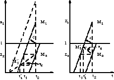
If the group velocity vg for mode n is zero, all particles in front of the test particle contribute to the wake seen by it for this mode. If vg is not zero, it is represented by an angle in the longitudinal position versus time graph (Figs. 1 and 2). Test particle M2 is influenced by particles in front, such as M1, but the energy flowed from position M´1 of M1. All particles influencing M2 at its position were on segment M2 M´1. The limit is given by the intersection of M2 M´1 with the structure entry face (vg > 0) or with the structure exit face (vg < 0). Designating the structure length by l,
vg > 0: 0 < z2 < vg (z1-z2)/(c-vg)
vg < 0: l-vg (z1-z2)/(c+|vg|) < z2 < l
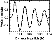
Code MAFIA has been used to calculate the wake potentials
resulting from crossing through a small number of cells of the
structures by a truncated Gaussian distribution of charge travelling
along the structure axis or at 1 mm distance from it [10], in
parallel with measurements [4]. These potentials are given as
functions of distance S to bunch head. One can try to get mode
frequencies and loss factors by minimizing the differences between
these results and those of the convolution of the delta wake potentials
w(s) with the distribution. For longitudinal wake,
where n is the bunch half width, z is the distance
of the test particle from the structure entry, s is the distance
to the particle in the bunch. Limits are functions of S and vg.
The loss factor obtained for mode n = 2 is at least a factor of
100 smaller than for n = 1. A comparison of the input resulting
from MAFIA with the wake reconstructed by the convolution is shown
for 12 cells of a structure similar to the CTF ones. Transverse
potential decreases because of vg
(Fig. 3).
Code PARMTRACK follows each of the particles of a
beam through a given series of elements such as drifts, focusing
devices, dipoles, accelerating cavities. For calculating wakefields,
as for calculating space charge, it is necessary to know the particle
distribution at as many time steps as required by the precision.
After each step, the resulting changes in the momenta are superimposed
on the momenta due to the other fields. For the space charge,
the coordinates of all the particles at a given time are used.
For the wakefields, the coordinates of the particles at the time
they were sources of the energy flow are also important, as shown
above. Coordinates are reconstructed from a series of tables corresponding
to selected transverse planes, such as structure entry faces.
Accounting for multibunches and wakefields effects makes the calculations complex and limitation of the total number of particles, and therefore also of the number of particles per bunch, is necessary. The distribution is a truncated Gaussian one. A random choice in a Gaussian distribution would require too many samples. So, instead, positions of the particles are taken at centres of equally populated intervals of this Gaussian, giving as many particles as intervals. The series of positions (or phases) in a bunch is the series of increasing values thus obtained and normalized with the rms bunch length. Random permutations in the same series give, after having normalized with corresponding rms values, the initial coordinates x, dx/ds, y, dy/ds, dE/E for each particle. Coupling between initial x, dx/ds or initial y, dy/ds is possible.
For each of these particles, three other particles are derived with same longitudinal position but inverse signs on pairs (x, dx/ds) or (y, dy/ds), or both. The beam transverse symmetry imposed by the procedure suppresses a source of artificial wakefields.
By default, the distribution in successive bunches
is the same as the one in the first bunch. A variation of the
energy from bunch to bunch and a variation of the bunch centre
transverse position can be specified.
A series of a maximum of 6 transfer structures, each of 0.6 m, is installed in the drive beam line after acceleration and compression devices. In longitudinal and in dipole modes, the loss factors are negligible for frequencies higher than the first one. Damping of the transverse mode is vital to restrain the beam in the apertures (r = 7.5 mm for structures, 12 mm for quadrupoles). The difference between the fundamental frequency and the dipole one is also important.
| longitudinal | transverse | |
| frequency (GHz) | 29.9855 | 29.9625 |
| V/pC/m (/m2) | 55.2 | 1.63 104 |
| vg | c/2 | c/2 |
| damping factor (0.1 m) | no | 0.5 |
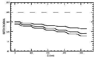
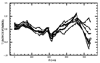
By the effects of group velocity, structure length and bunch separation, steady state is reached after 12 bunches. The energy variation with z is shown (Fig. 4), with the position of the structures.
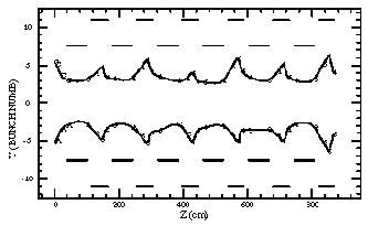
Focusing is provided by triplets in intervals between structures, with identical forces (0.904 T, 0.494 T). The input emittance is 1000 mm mrad in each plane. Transverse effects are caused by the following displacements:
| systematic | random | |
| bunch to bunch shift () | 100 | 50 |
| structures | 0 | 100 |
| quadrupoles | 0 | 20 |
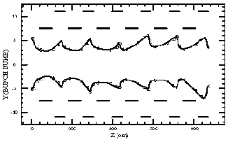
The envelope is shown for a calculation made with 17 bunches and 84 particles per bunch (Fig. 5). Alphanumeric digits indicate to which bunch the particle at the limit is related.
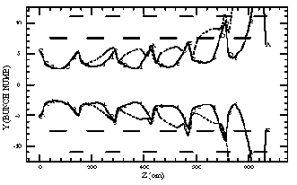
Positions of the centres of each bunch cross over but with a similar variation with z (Fig. 6).
The correlation between the variation of the maxima
of the envelopes and the variation of the central positions of
the bunches may be used for displacing the triplets in a one to
one correction scheme. The chosen BPMs allow averaging on the
transverse position of the 5 successive bunches whose energies
are close to the overall average. Results (Fig. 7) show the good
transmission of the beam.
In another study, the parameters were more severe: 21 nC for 1 mm rms bunch length, 43 MeV input energy, damping of 0.3 between bunches.
In this case, the lowest energy at the end is 20
MeV. Focusing was varied from (749 T, 441 T) to (663 T, 390 T)
from triplets 1 to 6, by more than required by the energy drop,
but avoiding over-focusing. The beam is lost on structure 5. With
correction, the amplitude of the average position of the bunches
is brought from 3 mm to 2 mm: the beam is lost in the middle of
structure 6 (Fig. 8). More damping is needed if 6 structures are
used.
I would like to thank all members of the CLIC study
group for the discussions of the results, and also G. Guignard,
I. Wilson, J.P. Delahaye for their constant support. Particular
thanks are due to J. Apostolakis, who suggested and succeeded
in writing a version for parallel processing.
[1] The CLIC Study Group, CTF2 Design Report, CLIC Note 304, 1996.
[2] B. Mouton, The PARMELA Program, LAL/SERA 93-455.
[3] J.A. Riche, Tracking Particles with wake fields and space charge, Proc. IEEE Particle Accel. Conf., Dallas, 1995, p. 2367.
[4] G. Carron, L. Thorndahl (private communication).
[5] C.D. Johnson, Two-particle model with zero emittance and centre of gravity motion, 1996 (unpublished).
[6] S. Fartoukh, Statistical analysis of a beam line with misalignment defaults, 1996 (unpublished).
[7] J. Apostolakis, Parallel simulation for high energy physics, Proc. High Performance Computing and Networking, Brussels, 1996, p. 258.
[8] L. Thorndahl, 30 GHz longitudinal wake and compressed output pulse of the CLIC transfer structure (CTS), CLIC Note 218, 1994.
[9] L. Thorndahl, Beam loading compensation and 30 GHz power requirement for multibunching, CLIC Note 274, 1995.
[10] A. Millich, Optimisation of CTS design to match
new drive beam parameters, Proc. IEEE Particle Accel. Conf., Dallas,
1995, p. 1779.