The propagation of HOM-energy along an accelerator
channel can be described in terms of frequency dependent scattering
(S-) parameters of the individual elements of the channel. These
S-parameters can be measured for each element (cavities, couplers,
etc.) separately. Once they are known, it is possible to predict
the behaviour of any arbitrary combination of elements. As long
as only one waveguide mode propagates in the connecting pipes,
standard RF calibration schemes are applicable methods to measure
the three S-parameters of the representing two-port. In the presence
of additional modes - corresponding to higher frequencies - S-matrices
of higher dimensions have to be determined. Therefore we have
been developing an experimental method which allows for determination
of S-parameters in the regime of waveguide ports with several
propagating modes. The principles of the method as well as results
from measurements of normal conducting TESLA cavity models are
presented.
The TESLA HOM-damping scheme consists of two couplers
attached to either side of each cavity and a single absorbing
element in a 8-cavity module [1]. The latter
is intended to dissipate HOM-power propagating through the accelerator.
This leads to the question of how to measure RF power transmission
in a complicated structure at frequencies that may allow for the
appearance of more than only the funda-mental waveguide mode.
Therefore the problem exceeds the capabilities of the usual two-port
S-parameter measurement, which is only appropriate for a single
propagating mode. Even then the question of de-embedding the test
devices properties from the measurement results, being modified
by the necessary coaxial line-waveguide-adaptors, remains, but
it is similar to calibration problems in pure coaxial setups.
If more modes are present in the waveguides there was to our knowledge
no practicable method available to measure a multidimensional
S-matrix at an arbitrary (for a given number of modes) fixed frequency
(or a spectrum of them).
We performed measurements in the frequency range with only the
fundamental mode propagating (2.25 GHz to 2.95 GHz for 78 mm
diameter TESLA beam pipe) using a standard T
hrough-S hort-D
elay-calibration method (eg. [3]). For higher
frequencies we have been developing an alternate method that has
been tested now with two waveguide modes for a device measurement
and with three modes for a calibration of an adaptor at single
frequency points (see [4] for details).
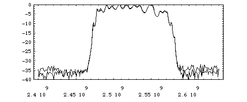
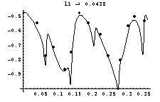
Fig. 1 shows
results from single mode S-parameter measurements of two 9-cell
cavities (compare [2] for details) using a
TSD-method for the adaptor calibration. With the knowledge of
the individual S-matrices one can calculate the result expected
for two cavities chained together. This calculation is plotted
in Fig. 1 together with the measured transmission
of the chain.
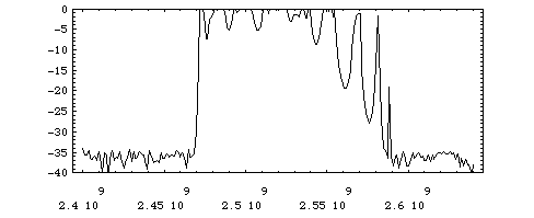
In Fig. 2 the calculated transmission through four identical cavities
is plotted. One observes a behaviour well known from filter cascades:
The slopes increase with the length of the chain.
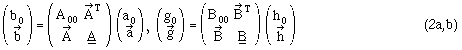
In the case of more than one propagating mode the S-matrix of an adaptor with one coaxial line (index 0) and n waveguide ports may be written as:
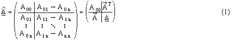
Herein the scalar A00 describes the reflection at the coaxial port, the vector the coupling from the coaxial line to each waveguide mode and the submatrix the reflection at the wave-guide flange, that may couple every mode to each other. The matrix is symmetric due to the reciprocity of the device. Like in the single mode case, the problem of determining the properties of a device splits into the calibration step - i.e. determination of the adaptors - and the measurement once the adaptors are known. Considering the number of unknowns (10 in the case of two modes at two waveguide ports) it becomes clear, that a single measurement with two completely known adaptors, which gives three numbers (two reflection, one transmission quantity), is not able to provide a sufficient amount of information. Thus one has to use different pairs of known adaptors for a number of subsequent device measurements. To keep the calibration effort as small as possible we take only two fixed adaptors and combine them with various delay line lengths (see Fig. 3). In the same manner we use a short (which is one of the very few reliable broadband standards in waveguide technique) and different delay line lengths to calibrate the two adaptors.
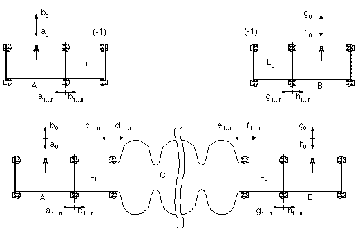
If we consider a setup with two adaptors A and B, a test device C and two connecting waveguides with lengths L1 and L2 (see Fig. 3), we are able to write down all signals, related by S-matrices:
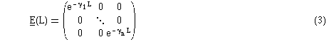
All the submatrices are (n x n)-dimensional, especially holds for the waveguide of length L and the phase constants gj:
Using an additional abbreviation
and with respect to the fact, that the complete setup is just a coaxial line two port with a (2 x 2)-S-matrix
one finds after some calculations in order to eliminate all signal quantities (see [4]):
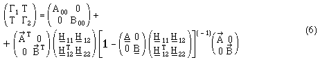
We shall refer to (6) as the
"complete model".
Equation (6) can be rewritten using
(we skip the discussion of the mathematical conditions)
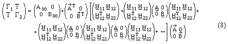
as a geometric matrix series. This expansion is useful as well as an approach for the numerical solution of (6) with a set of measurement data as for its physical interpretation. We denote (8) as the "reduced model". To simplify discussion, we restrict ourselves to the calibration problem, which is a special case of (6) (set all elements of C to 0 except the upper left block which is the negative identity). Then the complete model is
and its reduced version reads like:
Evaluating this in the case of two modes
shows that each term describes a possible signal
path from initial incidence to final detection. The same holds
for (8) but the expressions are much more
complicated. With the arithmetic derivation of (6)
we just did a summation over all signal parts, written in a very
compact way. To solve a set of equations (6)
with measurement data, we fit the data depending on L1, L2 in
the reduced model using the set of oscillations with wave numbers,
given by the combinations of the known phase advances. The amplitudes
of the lowest and therefore dominant frequencies are functions
easy to be solved for the S-parameters (compare (11))
(due to some quadratic expressions some of the signs remain ambiguous).
This procedure works as well for an adaptor calibration as for
a complete measurement; in the latter case we have to fit with
respect to two parameters.
The main effort in the setup had to be spent in the
realization of the various delay line lengths. This has been done
by building two adaptor systems sliding in two fixed waveguides.
They are driven by stepping motors with spindles that allow for
a nominal position resolution of 6.25 m. The RF equipment consists
of a HP8753C-6 GHz-network analyzer. The components are computer
controlled using LabVIEW ,
the data evaluation is done with Mathematica
.
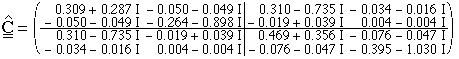
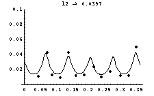
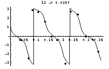
One of the adaptors has been measured at 4.5 GHz with three propagating modes (TE11, TM01, TE21). The results are:
We insert these parameters into the reduced and the
complete model (Fig. 4) plotted against L1
and add the measurement points. We observe a sufficient agreement
of the reduced model and a very good one of the complete model.
This may be explained by the limited amount of wave numbers contributing
in the reduced model, whereas the complete model covers all of
them up to an infinite degree of multiple reflection.
Introducing a normalized error function
we studied the error-sensitivity of the result by
adding some random offset within a certain part of each parameter
value. Fig. 5 shows the result of 100 attempts
together with the error function of the unperturbed S-parameters.
We found the majority of attempts revealing an increased error,
confirming that the unperturbed S-parameters are a very good (but
not optimal) approximation to the real values.
The S-matrix of the TESLA 9-cell copper cavity has been measured at 3.0968 GHz. At this frequency the TE11 and the TM01-mode propagate. After the calibration runs of the adaptors (we skip these results) we find from (8):
The reason of the value of C44 being about 20% greater
1 is not yet clear. Probable causes might be the small number
of measurement points (13 for L1 and L2, leading to an 13x13-array)
or a temperature drift, that has been observed during the measurement
time of about 1 hour. Again, we tested the complete model and
found a sufficient though not extremely good agreement (Fig. 6,
7).
The TSD-calibration technique is a useful tool to
calibrate coax-waveguide-transitions if only one mode is propagating.
To expand measurements in the frequency range of several waveguide
modes we have been developing a new method for multimode S-parameter
measurements showing encouraging results in first tests. These
evaluations will continue to specify the capabilities of the method.
In further investigations we shall try to resolve additionally
degenerated modes, especially different polarisations.
This work was supported by DESY and by BMBF under
contract 060f359.
[1] D.A. Edwards (Ed.): TESLA TEST FACILITY LINAC - Design Report (TESLA-Rep. 95-01),
DESY, Hamburg March 1995
[2] H.-W. Glock,
M. Kurz,
P. Hülsmann,
W.F.O. Müller,
U. Niermann,
C. Peschke,
H. Klein: Energy Propagation through the TESLA Channel: The Regime
of the First Waveguide Mode (TESLA-Rep. 95-07), DESY,
Hamburg April 1995
[3] G.F. Engen, C.A. Hoer: "Thru-Reflect-Line":
An Improved Technique for Calibrating the Dual Six-Port Automatic
Network Analyzer, IEEE-Trans.-MTT 27
, 12 (Dec. 79), pp. 987
[4] H.-W. Glock,
P. Hülsmann,
C. Peschke,
W.F.O. Müller,
H. Klein: Energy Propagation through the TESLA Channel: Measurements
with Two Waveguide Modes (TESLA-Rep. 96-07), DESY, Hamburg June
1996