The proposed Los Alamos National Laboratory Long Pulse Spallation Source (LPSS) design consists of a 1 MW neutron spallation target fed by a pulsed proton beam from the Los Alamos Neutron Science Center (LANSCE, formerly LAMPF) accelerator. This proton beam would have a repetition rate of 60 Hz and a pulse length of 1 ms for a duty factor (DF) of 6%. An average/peak current of 1.25 mA/21 mA would be required for an 800 MeV beam to provide this power at this duty factor. The spallation target would reside in what is now called Area A and would use the H+ beam. The LANSCE accelerator would also be required to simultaneously deliver H- beams to the Manuel Lujan Jr. Neutron Scattering Center (MLNSC) and the Weapons Neutron Research (WNR) facility at the requisite duty factors and currents. LANSCE currently delivers 16.5 mA peak of H+ beam at 120 Hertz, with a 625 µS beam pulse length. H- beams are accelerated for use in MLNSC and WNR.
In November of 1995, operation of the linac shifted to the LPSS pulse parameters, except for the peak current which remained at the 16.5 mA production level. In addition to delivering 800 kW of H+ proton beam to physics production targets, H- beams were simultaneously delivered to customers for the proton storage ring feeding MLNSC, and to researchers using the WNR facility. Performance of the RF powerplants for the 201.25 MHz drift tube linac (DTL), the 805 MHz side-coupled linac (SCL), and the associated electronics is described [1].
The conclusion of the experiment is that the LANSCE
linac can be upgraded through modest improvements to drive a 1
MW LPSS.
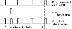
The objective of this experiment was to simultaneously deliver an evenly spaced 60 Hz x 1 ms, 1 mA average , 800 MeV beam to Area A (800 kW beam, 80% of LPSS design), an evenly spaced 20 Hz x 600 ms, 70 mA H- beam to the PSR/MLNSC, and 60 Hz x 625 ms, 1 mA H- beam to WNR. These criteria were chosen because they represent the present beam parameters. Also, it represents an H+ peak current which is a large fraction of the LPSS design. The WNR and Area A beams (both at 60 Hz) were accelerated in the same RF pulses. The 20 Hz PSR beam was interleaved with those 60 Hz pulses. The parameters used during the test are shown in Table 1.
To achieve the above beam parameters, we operated
the RF at 80 Hz, spaced irregularly in a three on, space, one
on, space pulse sequence. Refer to Figure 1. Peak power was
maintained near the normal operation values, as peak beam current
did not increase.
Table 1: Nominal Beam Parameters Used During LPSS Demonstration Test
|
|
| |||
| |||||
The 805 MHz RF systems required a pulse length of
1185 µs, and therefore operated at a duty factor of 9.5%.
The 201.25 MHz RF systems required more time at the start of each
pulse to fill the cavities and stabilize the fields (1235 µs
pulse length). The 201.25 MHz duty factor was 9.9%
A description of the 201.25 MHz RF systems is given in a companion paper [2]. The RF power amplifiers (PA) driving DTL tanks 2 through 4 are operating close to their maximum average power ratings. DTL tank 1 uses the same PA tube for compatibility, operating at one-sixth of the power.
We measured the waveform of the voltage on the HVDC capacitor bank for Modules 2 - 4, the highest power systems. Module 2 was the only system requiring increased HV for
adequate headroom. This module was operating at the highest peak power, so it also had the highest plate current. With H+ beam on, the peak power for modules 2, 3 and 4 was 3.05, 2.54, and 2.71 MW, respectively. Because of the higher plate current, the plate modulator of module 2 had a large voltage drop across the pass tube components. This is seen in the comparative modulator voltage drops in the oscilloscope traces in Figure 2.
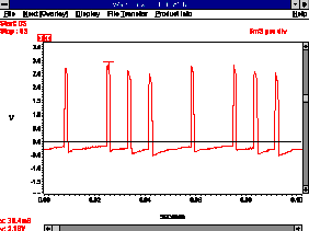
The ripple on the capacitor banks was observed (Module 2 shown in figure 3). Note that the stairstep for each pulse starts at a different voltage, repeating after 50 milliseconds.


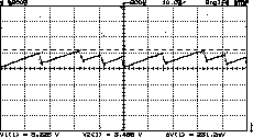
During the normal production of 1995, the capacitor bank was operated at 31.5 kVDC, but had to be increased to 33 kV during this test.
During the beam production period in 1995, the Burle
7835 triode PA for Modules 2 - 4 operated at about 90% of their
administrative limit of 250 kW average plate power dissipation
[2]. It had been hypothesized that for a constant duty factor,
operating with lower repetition rates and longer pulses would
result in lower dissipation. As the repetition rate was reduced
on Nov. 28 from the original 120 Hz to the new 80 Hz condition,
plate power dissipation was found to drop as shown in Table 2.
This 8 to 10 kW reduction was more than could be accounted for
by the slight adjustment in DF alone. With only 2/3 of the number
of pulses per unit time, the number of turnon transients is reduced,
the time where the PA operates with high VSWR during the DTL fill
time. This accounts for the reduced plate power dissipation.
| |||
| |||
|
The 805 MHz RF systems for the SCL (also called coupled cavity linac or CCL) are comprised of forty-four Varian and Litton klystron amplifiers operating with a pulsed mod anode. Each klystron is capable of supplying 1.25 MW of RF power. RF drive is modulated for field amplitude control. They are spaced over 731 meters of linac and increase the proton beam energy from 100 to 800 MeV. Six to seven klystrons are clustered with a HVDC capacitor bank.
In a series of tests in 1993, the cluster of klystron amplifiers at modules 18 through 24 was operated at 12% DF and 60 Hz repetition rate. These tests were performed without beam, with extreme (2 ms) pulse length. It was determined that the practical DF limit comes from the maximum current from the high voltage power supplies. Browman [3] reported that the maximum peak beam current of 25 to 30 mA was limited by the available peak power from the klystrons. During the 1995 LPSS experiment, we measured the peak power of module 48, with calibrated couplers and instrumentation, for the 16.5 mA H+ beam of the LPSS test. Close attention was given to the low level RF controls and the amount of work to adjust them for this test.
Due to the increased demands on the RF powerplant
by the high current, long pulse H+ beam, in addition to the 20
Hz H- beam, the 805 MHz RF capacitor banks experienced significant
voltage droop. This droop problem was exacerbated by the irregular
pattern of pulses. Figure 4 depicts the droop and pattern of klystron
cathode current for Module 48. The relationship of cathode current,
Ik , to capacitor bank voltage, Vc , is
Ik=kVc3/2. A reduction in capacitor
bank voltage results in reduced klystron cathode current and overall
gain. Reduced gain in the klystron results in reduced loop gain
and causes the control system to increase its drive power. This
requires the control system to operate over a larger dynamic range
than in past operational modes.
The controls for the SCL RF powerplant required considerable hands-on tuning, which was made more difficult by the length of the accelerator. The asymmetric pulse train of the RF made the capacitor bank voltages vary from pulse to pulse. To compensate, the capacitor banks were operated at higher levels. For certain modules, it took adjustment of the klystron focus magnet currents to move tube gain irregularities out of the nominal control range of the system. Otherwise these anomalies would perturb the control loops, causing instability.
In order to project the requirements for 21 mA
beam operation, the power signals were carefully measured at 16.5 mA
of peak beam current. The output power for the Module 48
klystron is representative of Sector H, which traditionally has
a high power load as a result of the beam loading. The directional
coupler and the diode detectors were calibrated to back out the
actual power consumptions during the beam operation:
Predicted beam loading at 16.5 mA peak current
(16.5 mA X 16.81 MV) [tank 48] 277 kW
Measured incident power without beam
(Resistive Losses only) 607 kW
Measured incident power with 16.5 mA peak current
(Resistive losses plus beam loading) 872 kW
Measured beam loading with 16.5 mA peak current
(872 kW - 607 kW) 265 kW
Predicted beam loading at 21 mA peak current
(21 mA X 16.81 MV) 353 kW
Predicted power required for 21 mA LPSS beam ~1000
kW
The measured power is within a 4% agreement with
the design code estimated resistive copper losses including corrections
for bridge coupler losses and the SCL measured Q [4].
Corrected design code estimate 631 kW
Measurement 607 kW
In comparing with the measured values, we must allow for some small difference introduced in fine tuning the beamline optics by adjusting the beam output energy with Module 48 power.
The 805 MHz klystrons are rated at 1.25 MW
peak power and are consistently tuned to that power level into
a matched load. Driving into the mismatched load of the accelerating
cavity does effect the klystron output, depending on the phase
and magnitude of the reflection. The expected 1 MW peak power
requirement for 21 mA of beam leaves 250 KW for control margin
for closed-loop control and for the mismatch. It is felt that
the 805 Mhz RF powerplant will be able to supply the needed power
without needing significant upgrading.
Future Direction for RF Systems at LANSCE
Additional tests in coming months will examine operation at 21 mA peak H+ beam current while delivering beams to the other users. This will, of course, require a reduction of the DF for the present 201.25 MHz system. A project to eliminate the IPA plate modulators, and operate the tubes from stand-alone DC power supplies has been funded to improve reliability, simplify the RF power system, and reduce the amount of droop in the IPA RF output power. An adaptive feedforward controller is proposed to be added to the low level amplitude/phase controllers to improve response to repetitive beam transients, temporal and cyclic drifts in tune, and component changes or gain drifts inside the controlled loop. These improvements are offered to improve the LANSCE DTL RF system for the present beams and for the proposed LPSS beam.
For 21 mA LPSS operation, we have proposed a new RF amplifier chain. The new PA systems would not require high-level plate modulation for amplitude control but would operate with DC from the capacitor bank. Without the modulators, the plate voltage drop would disappear, raising the peak power capacity of modules 2 through 4 while maintaining low capacitor bank voltages. Duty factor would not be a limitation. The tank window will be examined with improvements to handle the higher peak voltages and currents. RF circulators are proposed to eliminate troublesome reflected power [2].
Due to the large number of systems in the SCL RF
powerplant, any proposed modification must be analyzed for benefit
versus the individual unit cost. This has limited the overall
upgradability of the SCL RF systems in the past to minor improvements.
Upgrades must be reviewed in light of this philosophy. Work is
underway to improve the controllability, the power monitoring
instrumentation, the uniformity of klystron parameters, and the
inventory of spare klystrons. There is much more room for significant
modification in the 201 MHz DTL powerplant, with only four modules.
The LPSS experiment was carried out through the combined
efforts of the AOT-6 Beam Delivery and Physics Teams and the AOT-5
RF Team. They were instrumental in making the adjustments and
changes in a timely and coordinated manner, over a continuous
period encompassing 48 hours.
[1] L. Rybarcyk, J. Lyles, et al, "LPSS Demonstration using the LANSCE Linear Accelerator," AOT-6-96-44, Tech. Report.
[2] J.T.M. Lyles and C. Friedrichs, "LANSCE 201.25 MHz Drift Tube Linac RF Power Status", these proceedings .
[3] Pilac Technical Note by A.D. Browman, "Performance Limits of the LAMPF 805 MHz RF System", LA-UR-94-839, 1994.
[4] G. R. Swain, " LAMPF 805 MHz Accelerator Structure Tuning and Its Relation to Fabrication and Installation," LA-7915-MS, 1979.