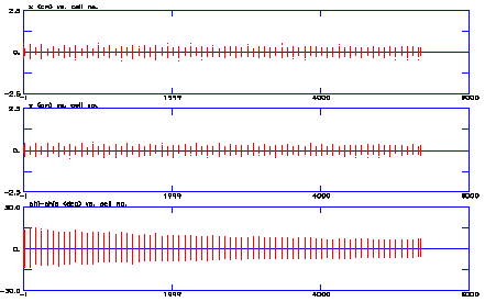
The accelerator based production of tritium calls for a high-power, cw proton linac. Previous designs for such a linac use a radio-frequency quadrupole (RFQ), followed by a drift-tube linac (DTL) to an intermediate energy and a coupled-cavity linac (CCL) to the final energy. The Los Alamos design uses a high-energy (6.7-MeV) RFQ followed by the newly developed [1] coupled-cavity drift-tube linac (CCDTL) and a CCL. This design accommodates external electromagnetic quadrupole lenses which provide a strong uniform focusing lattice from the end of the RFQ to the end of the CCL.
The cell lengths in linacs of traditional design
are typically graded as a function of the particle velocity. By
making groups of cells symmetric in both the CCDTL and CCL, the
cavity design as well as the mechanical design and fabrication
is simplified without compromising the performance. At higher
energies, there are some advantages of using superconducting rf
cavities. Currently, such schemes are under vigorous study [2].
Here, we describe the linac design based on normal conducting
cavities and present the simulation results.
The linac for the production of tritium calls for 100 mA of cw proton beam to be delivered onto a production target. The main challenge in the design comes from the hands-on maintenance requirement of the entire linac by way of permissible beam loss along its length. Thus, elimination of known causes of beam-loss and control of transverse emittance growth (implying larger transverse spread of beam particles) are of utmost concern in the design of such a linac. In the room temperature design, we minimized the number of transitions between accelerating structures. In contrast to earlier designs [3], the only transition we have is between the RFQ and the CCDTL. In addition to eliminating all but one transition, we do not have a separate matching-section between the RFQ and the CCDTL. Instead, the transport properties in both the transverse and longitudinal motion are tailored to be continuous at the end of the RFQ and the beginning of the CCDTL, thus avoiding a discontinuity in the restoring forces experienced by the beam.
A schematic of the linac is shown in Fig. 1. It consists
of an RFQ followed by a CCDTL and a CCL. The RFQ accelerates the
beam from 75 keV to 6.7 MeV and the CCDTL takes the beam to 100
MeV. A CCL accelerates the beam to a final energy of 1.3 GeV.
The cw RFQ for the APT linac produces a 100-mA beam of protons with an output energy of 6.7 MeV. An engineering drawing of the RFQ is contained in Ref. 3. The conceptual design is described in complete detail elsewhere [3-4]. This is an 8-m long rf structure consisting of four 2-m-long segments that are resonantly coupled together. Each segment is a resonant structure assembled from two 1-m-long brazed sections.
The RFQ design uses an improved beam-dynamics code [5] that includes multipole field effects. It has been benchmarked successfully against other codes [6]. The transverse current limit is greater than 240 mA throughout the length of the structure. The longitudinal current limit exceeds 150 mA beyond the 1-MeV point. The peak surface field along the length of the vane-tips does not exceed 1.8 times the Kilpatrick limit.
In the high-energy part of the RFQ, we specially
tailor the vane-tip modulation to increase the longitudinal focusing
strength thereby reducing the phase width of the exit beam.


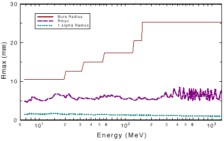
Effective shunt impedance for cavities as a function of are calculated by the 2-D code SUPERFISH. Except for the very beginning of the coupled cavity structure (10 MeV), we keep the real-estate shunt impedance ZT2 above 35 M/m. Consistent with this choice, we open up the bore radius as quickly as practicable. Figure 3 shows the average real estate shunt impedance as a function of energy while the variation of the bore radius along the length of the linac is shown in Fig. 8.
For power partitioning, each supermodule (chains of up to 160 coupled-accelerating cells driven in common by multiple klystrons) is fed by 4 to 6 klystrons. This concept permits the addition of an extra klystron to each supermodule i.e., operate each supermodule with 5 to 7 klystrons, thus providing redundancy in the system.
The design of the transition region involved tailoring
the end of the RFQ as well as first few periods of the CCDTL.
General design philosophy of this region is described in Ref.
8 while the detail is contained in Ref. 7. Following this capture
section, there is a quasi-adiabatic ramp in both the synchronous
phase s and the field accelerating gradient E0T.
Both are initially ramped adiabatically up to 11.4 MeV. We start
at s= -600 to assure capture of the beam
in the "bucket". We then ramp down s and ramp up
E0T adiabatically while maintaining a large ratio between
the bucket and the beam-size. The structure E0, real
estate E0, real-estate E0T, and acceleration-rate
variation as a function of energy are shown in Fig. 4. The design
goal was to obtain a smooth variation in the real-estate E0T
until a predetermined value of real-estate E0T is reached.
ZT2 values dictate the bore radius which does not vary
smoothly with energy. Since transit time factor is also dependent
on the radius, the structure E0 does not show a continuous
variation as seen in Fig. 4. At 155 MeV, we achieve a real-estate
E0T of 1.3 MV/m which is held constant thereafter to
conserve power. The design parameters of the entire linac are
given in Table 1.


| Parameter | RFQ | CCDTL | CCL |
| Energy (MeV) | 0.075-6.7 | 6.7-99.6 | 99.6-1300 |
| Frequency (MHz) | 350 | 700 | 700 |
| Beam Current (mA) | 100 | 100 | 100 |
| Aperture Radius (mm) | 2.3-3.4 | 10.0-17.5 | 17.5-25.0 |
| Cavity E0T (MV/m) | 1.38 | 1.095-1.574 | 1.574-1.485 |
| Real Estate E0T (MV/m) | 1.38 | 0.410-1.180 | 1.180-1.300 |
| Synchronous Phase (deg) | -90 to -60 | -60 to -30 | -30 |
| Real Estate ZT2 (M/m) | - | 18-33 | 33-47 |
| Quad Lattice | - | FODO | FODO |
| Quad Length (mm) | - | 30.0 | 30.0 |
| Quad Gradient (T/m) | - | 87.5 | 87.5 |
| Trans. Emit. ( cm. mrad)+ | 0.022 | 0.023 | 0.023 |
| Long. Emit. ( deg. MeV)+ | 0.214* | 0.450** | 0.482** |
| Aper. rad. / rms beam-size | - | 5-13 | 13-26 |
The computer code PARMILX [9], a modified version of PARMILA, was used to both generate and simulate the performance of the linac beyond the RFQ. An end-to-end simulation was performed with 100,000 macro-particles at the entrance to the RFQ. A 4-D waterbag distribution was assumed at the input.
Transverse phase space distributions at 1.3 GeV for full current of 105 mA are shown in Fig. 5. Beam profile plots for full current from 155 MeV to 1.3 GeV are shown in Fig. 6. No profile oscillations indicate a good match in the transition region. Longitudinal and transverse emittances vs. energy are


plotted in fig. 7. There is essentially
zero transverse emittance growth from 6.7 MeV to 1.3 GeV. Since
the real-estate accelerating gradient E0T is constrained
to 1.3 MV/m above 155 MeV, the longitudinal focusing grows weaker.
As a consequence, a longitudinal emittance growth of 15 % is observed.
However, this is of little concern since longitudinal beam-size
is very small compared to the bucket-size and luminosity requirements
are not important for this application. Figure 8 shows the relationship
between beam-size (rms), aperture-size, and maximum radius of
a particle as a function of energy. This particle is the outermost
one in the distribution, outside the core distribution and constitutes
a particle in the halo. Even at higher energies, this particle
does not occupy more than 25% of the bore.

We have described the conceptual design for a high-current
normal-conducting linac specifically designed to deliver a high-power
proton beam on an extended target. A very high bore- to beam-size
ratio was achieved at higher energies where beam-loss is of concern.
Simulations show zero transverse emittance growth for the entire
linac.
[1] J. H. Billen et al., "A New rf Structure for Intermediate-Velocity Particles," Proceedings of the 1994 Linear Accelerator Conference, Tsukuba, Japan, August 21-26, 1994.
[2] G. Lawrence et al., "Conventional and Superconducting RF Linac Design for the APT Project," this conference.
[3] Los Alamos National Laboratory APT Topical Report, LA-UR-95-1480, March, 1995.
[4] L. M. Young, "Segmented Resonantly coupled Radio Frequency Quadrupole (RFQ)," Proceedings of the 1993 Particle Accelerator Conference, Washington D.C., May17-20, 1993.
[5] "RFQ Design Codes," Los Alamos National Laboratory Document, LA-UR-96-1836, May, 1996.
[6] N. J. Diserens, Atomic Energy of Canada Limited Research Company Internal Report (unpublished), RC-1048, July, 1993.
[7] S. Nath et al., "Front-End Physics Design of APT Linac," this conference.
[8] J. H. Billen et al., "Smooth Transverse and Longitudinal Focusing in High-Intensity Ion Linacs," this conference.
[9] H. Takeda et al., "Modified PARMILA Code
for New Accelerating Structure," Proceedings of the 1995
Particle Accelerator Conference and International Conference on
High Energy Accelerators, Dallas, Texas, May 1-5, 1995.
* Work supported by the US Department of Energy.