The accelerator for the Accelerator based Production of Tritium (APT), uses a radio-frequency quadrupole (RFQ), followed by the newly developed [1] coupled-cavity drift-tube linac (CCDTL) and a coupled-cavity linac (CCL). The production target requires the APT linac to deliver a 100-mA proton beam with an energy of 1.3 GeV to 1.7 GeV. The main challenge in the design comes from the requirement to minimize beam loss. Hands-on maintenance of the entire linac requires very little beam loss.
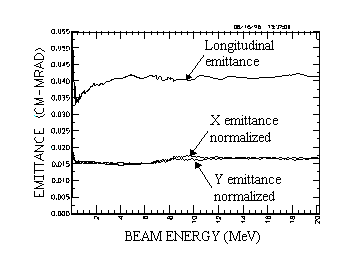
Recent studies indicate that mismatch is the single most important factor leading to beam-halo formation. Beam-halo can lead to beam loss and activation of the linac. A mismatch causes the beam size to oscillate about the equilibrium value. In practice, a mismatch usually occurs at transitions in the transport lattice such as the transition between an RFQ and a CCDTL or drift-tube linac (DTL). Traditionally, "matching sections" match the beam from one to the next structure. However, since matching is never very adiabatic, it can introduce emittance growth at abrupt lattice transition. Low energies specially enhance these effects. Here, we describe the front end of the linac and show the performance of this design. Figure 1 shows virtually no emittance growth of the beam as it moves through the current-independent transition between the RFQ and the CCDTL.
In this paper we define the 'front end' of the APT linac as the RFQ and a portion of the CCDTL. This portion provides a 100-mA proton beam with an energy of 20 MeV. As noted earlier, there is no matching section between the RFQ and the CCDTL. The transverse focusing lattice beyond the RFQ is a FODO with a constant focusing period of 8, where is the proton velocity relative to the speed of light and is the free-space wavelength at the CCDTL resonant frequency of 700 MHz.
The RFQ for APT, designed to accelerate a 100-mA proton beam to 6.7 MeV, will be the highest energy RFQ ever built. References [2,3] describe the detailed conceptual design. The 350-MHz RFQ operates at a subharmonic of the 700-MHz CCDTL. It is an 8-m-long rf structure consisting of four resonantly-coupled sections. In the high-energy part of the RFQ, we specially tailor the vane-tip modulation to reduce the phase width of the exit beam. The CCDTL can directly capture this RFQ output beam and does not require a separate matching section.
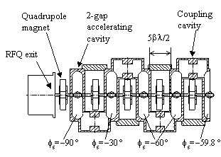
The CCDTL accelerator up to 20 MeV uses two types of cavity configurations. The first part has 2 gaps per cavity with one cavity between quadrupole focusing magnets. At about 8 MeV the configuration changes to three gaps per cavity. Figure 2 shows the cavity configurations at this interface. The change from two to three accelerating gaps per cavity in the CCDTL mainly increases the acceleration efficiency. From a beam-dynamics point of view, these structures are indistinguishable. The entire accelerator beyond the RFQ consisting of CCDTL and CCL maintains the 8 FODO transverse focusing lattice. Thus, the only transition the beam encounters is the one shown in Fig. 3 between the RFQ and the CCDTL at 6.7 MeV.
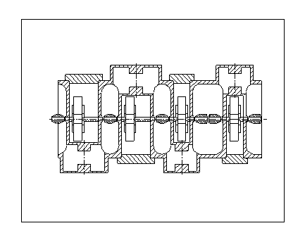
The first two gaps, which are in the first CCDTL cavity following the RFQ, provide no acceleration. This first cavity provides only longitudinal focusing and takes the place of a buncher cavity. Unlike conventional buncher cavities, this cavity is an integral part of the CCDTL structure. The resonantly coupled structure locks the phase and amplitude of each cavity to the phase and amplitude of its neighboring cavities through side coupling cavities. The relative longitudinal spacing between cavities sets the synchronous phase. The third cavity starts a quasi-adiabatic ramp in both the synchronous phase and the field amplitude. The synchronous phase starts at 60 and provides the large longitudinal acceptance needed in the early part of the CCDTL. The doubling of the frequency at this transition requires the large longitudinal acceptance. The chosen amplitude gives the same zero-current phase advance per unit length as at the end of the RFQ.
An earlier design of the APT [2] accelerator used a 350-MHz DTL with electromagnetic quadrupoles after the RFQ. The DTL required a relatively high-energy beam (7 MeV) from the RFQ to make room for the quadrupoles inside the drift tubes. The CCDTL structure has replaced the DTL in the present design of APT. The CCDTL structure does not constrain the quadrupoles to fit inside drift tubes. Therefore, it could accept beam from the RFQ at a comparatively lower energy. However, a lower energy would mean the loss of a major benefit, the current-independent transition from the RFQ to the CCDTL.
In the design of the APT accelerator we have reduced the transverse focusing strength in the high-energy end of the RFQ and increased the longitudinal focusing strength. In typical RFQs the accelerating gradient and the longitudinal focusing strength fall off rapidly at higher energies. Increasing the vane gap and the gap voltage in the high energy region of the RFQ maintains both the accelerating gradient and the longitudinal focusing strength. Smoothly varying the synchronous phase from 33 at 3.0 MeV to 40 at 6.5 MeV also helps maintain the longitudinal focusing strength. Varying the synchronous phase quickly to 55 in the region from 6.5 MeV to 6.7 MeV helps compensate for the loss of longitudinal focusing in the drift between the RFQ and CCDTL.
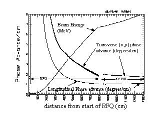
Figure 4 shows the zero-current phase advance per unit length, which is a measure of the focusing strength, in the RFQ and the first section of the CCDTL up to 8 MeV. Note that the transverse and longitudinal focusing strengths are nearly the same before and after the transition between the RFQ and CCDTL. This is the feature that makes the transition current independent. The focusing period in the RFQ is 1.0 at 350 MHz while in the CCDTL the focusing period is 8 at 700 MHz. Therefore, the focusing period in the CCDTL is 4 times the length of the focusing period in the RFQ. The zero-current transverse phase advance at the high energy end of the RFQ is 20 per period. Early designs of the RFQ had stronger transverse focusing at the high energy end. Increasing the aperture radius near the high energy end of the RFQ reduced the transverse focusing. This change costs in terms of rf dissipated power. The rf power dissipated on the cavity walls increased from 12 to 13 watts/cm2. However, this change made the transverse focusing strength per unit length nearly continuous at the transition from the RFQ to the CCDTL. It would be difficult, if not impossible, to reduce the transverse focusing strength to this level at lower transition energies. An alternating-gradient quadrupole channel (FODO) provides the transverse focusing in the CCDTL. The transverse focusing strength of this channel in the CCDTL is ~80 per period which is the same phase advance per unit length as in the RFQ. The optimum focusing strength for the smallest beam size is about 80 per period.
The last cell in the RFQ is a transition cell [4] that reduces the vane modulation to zero from its value in the next to last cell. The vane tips end with an exit-fringe-field region [5]. Adjusting the length of the fringe-field region provided Twiss, or Courant-Snyder, beam parameters that matched the beam to the quadrupole focusing channel of the CCDTL. This eliminated the need for a transverse matching section between the RFQ and the CCDTL. It will be possible to adjust the match because the quadrupoles in the CCDTL are electromagnets. The difficulty will be detecting a mismatch with the beam diagnostics. PARMILA simulations show that a small mismatch will be extremely hard to detect.
This design has no separate longitudinal matching section. The longitudinal focusing strength in the RFQ is the same at the end of the RFQ and beginning of the CCDTL. However, between the end of the RFQ transition cell and the beginning of the CCDTL, there is no longitudinal focusing. Compensation for this loss in the longitudinal focusing is necessary. A slight increase in the longitudinal focusing in the last few cells of the RFQ provides part of the needed compensation. However, the CCDTL provides most of the compensation. Increasing the amplitude of the first CCDTL cavity and operating it in the buncher mode (s = 90) provides most of the compensation. Reducing the longitudinal focusing in the second cavity balances the increased longitudinal focusing in the first cavity. This reduction comes from changing the synchronous phase of the second cavity to 30 from the nominal 60. The codes PARMILX [6] and PARMTEQM [7] provided the information to make adjustments of the field amplitude in first cavity and the synchronous phase of the second cavity. Adjustment of the cavity-to-cavity coupling in the CCDTL will provide the correct relative field amplitudes. The longitudinal match relies completely on these simulations because no beam diagnostics exist that could provide the necessary information about the actual beam to adjust the match.
The computer code PARMILX designs the cavity lengths and performs the particle-dynamics simulation for the entire linac beyond the RFQ. Figure 5 (a-c) shows the x beam profiles (top) and beam phase profiles (bottom) from multiparticle simulations for full current (100 mA), ~ half current (55 mA) and zero current. There were no adjustments to the transition region for the different cases. No profile oscillation's indicative of mismatch conditions attests to current independence matching between the RFQ and the CCDTL. Figure 5 (d) shows the profile and phase plot for the case when the RFQ vane voltage is 5% above the nominal design value. In this case, there is a slight mismatch in the phase centroid. The higher voltage changes the phase of the exit beam slightly. The oscillations of the phase centroid are visible in the phase profile of Fig. 5 (d)
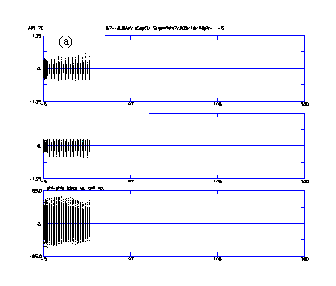

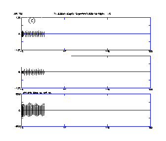
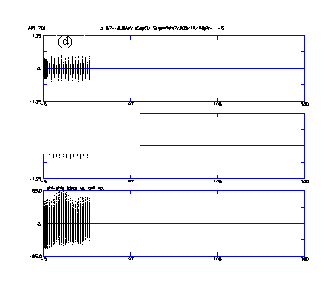
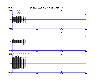
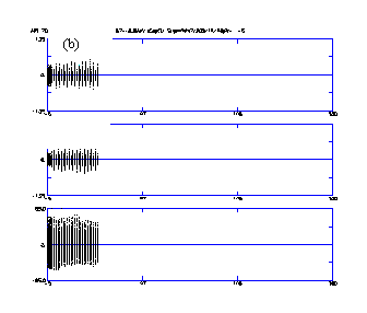
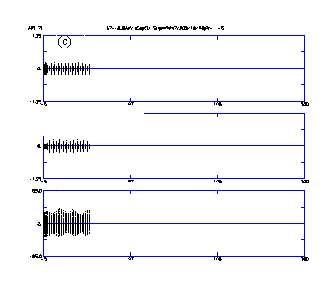
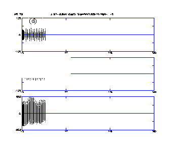
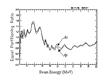
Figure 6 shows the equipartitioning
ratio for the front end. Equipartitioning [8] implies:![]() =
= ![]() =
= ![]() , where
, where ![]() and
and ![]() are the normalized emittances for
the transverse coordinates and
are the normalized emittances for
the transverse coordinates and ![]() is the
longitudinal emittance. The respective rms beam sizes are
is the
longitudinal emittance. The respective rms beam sizes are ![]() ,
,
![]() , and
, and ![]() . Both the
RFQ and the CCDTL have alternating gradient quadrupole focusing
channels. This type of focusing causes the
. Both the
RFQ and the CCDTL have alternating gradient quadrupole focusing
channels. This type of focusing causes the![]() and
and ![]() values to oscillate about the equilibrium
value ~
values to oscillate about the equilibrium
value ~![]() . Therefore, averaging over these
oscillations the equi-partitioning ratios Ax and Ay
plotted in Fig. 6 are defined as:
. Therefore, averaging over these
oscillations the equi-partitioning ratios Ax and Ay
plotted in Fig. 6 are defined as:
 .
.
We have outlined the approach for a current independent design of the front end of a high current APT linac. The use of the hybrid CCDTL structure in combination with a high-energy RFQ eliminates all but one transition in focusing period throughout the accelerator. In addition, the RFQ and CCDTL perform the matching at this transition without a separate conventional matching section.
[1] J. H. Billen et al., "A New RF Structure for Intermediate-Velocity Particles," Proceedings of the 1994 Linear Accelerator Conference, Tsukuba, Japan, August 21-26, 1994.
[2] Los Alamos National Laboratory APT Topical Report, LA-UR-95-1480, March, 1995.
[3] L. M. Young, "An 8-Meter long Coupled Cavity RFQ Linac," Proceedings of the 1994 Linear Accelerator Conference, Tsukuba, Japan, August 21-26, 1994.
[4] K. R. Crandall, "Ending RFQ Vanetips With Quadrupole Symmetry," Proceedings of the 1994 International Linac Conference, August 21-26, 1994 Tsukuba, Japan pp 227-229.
[5] K. R. Crandall, "RFQ Radial Matching Sections and Fringe Fields," Proceedings of the 1984 Linac Conference, GSI-84-11.
[6] H. Takeda et al., "Modified PARMILA Code for New Accelerating Structure," Proceedings of the 1995 Particle Accelerator Conference and International Conference on High Energy Accelerators, Dallas, Texas, May 1-5, 1995.
[7] K. R. Crandall et al., "RFQ Design Codes," Los Alamos National Laboratory Report LA-UR-96-1836 (May, 1996).
[8] M. Reiser "Theory and Design of Charged Particle Beams," John Wiley & Sons, Inc. New York, NY 1994, p 573-580.