The sum over damped modes, which provides
the main contribution to the transverse wake of the DDS, is replaced
by a Fourier-like integral of a spectral function over the propagation
band of the manifolds. We present comparisons to previous calculations,
assessment of appropriate domains of applicability, and applications
to the SLAC structure with matched and mismatched manifold terminations.
The recently completed prototype accelerating cavity for the NLCTA incorporates both damping and detuning (the DDS structure) of the higher order modes (HOM), with the objective of suppressing the transverse wakefield experienced by trailing bunches [1,2]. The current analysis of the structure is based upon an equivalent circuit model whose current form is described in [1]. We use the Bane-Gluckstern two band model [3], extended to include the damping manifold. The latter is represented by a rectangular TE10 waveguide mode, periodically shunted with a series LC circuit, with the shunt capacitively coupled to the TE component of the two band model. Each section of the structure is described by nine circuit parameters defined and determined as described in [1] along with the beam coupling parameters (cell kick factors [3]). In the following sections we the explain the the spectral function method, and compare it to our previous methods. The spectral function method is then applied to compute the dependence of the wake function on the manifold terminations.
The TE and TM cell excitation amplitudes
are related to the drive beam via the circuit equations. In matrix
form and in the frequency domain this relation takes the form:
where the quantities in the above expression
are defined in [1]. The elements in the above 2 by 2 matrix are
themselves N by N matrices, where N is the number of cells. ![]() and H are tridiagonal matrices which describe the coupled chains
of TM and TE resonant circuits, while Hx is the tridiagonal
matrix with vanishing diagonal elements which describes the
TE-TM coupling. R, which describes
the manifold, is also tridiagonal, while G, which describes the
coupling of the TE chain to the manifold, is diagonal. The diagonal
elements of H, G, and R are frequency dependent. Corresponding
to the above, each element of the column vectors are themselves
N element vectors. To further condense the notation we may also
write Eq. (1) in 2N by 2N matrix form
and H are tridiagonal matrices which describe the coupled chains
of TM and TE resonant circuits, while Hx is the tridiagonal
matrix with vanishing diagonal elements which describes the
TE-TM coupling. R, which describes
the manifold, is also tridiagonal, while G, which describes the
coupling of the TE chain to the manifold, is diagonal. The diagonal
elements of H, G, and R are frequency dependent. Corresponding
to the above, each element of the column vectors are themselves
N element vectors. To further condense the notation we may also
write Eq. (1) in 2N by 2N matrix form
The drive beam, represented by the N component vector B, couples only to the TM mode. We take it to be a point charge moving at velocity c and normalize it per unit charge per unit displacement. With this understanding it takes the form
where L is the periodicity length, ![]() the Bane-Gluckstern kick factor evaluated at the synchronous mode
and
the Bane-Gluckstern kick factor evaluated at the synchronous mode
and ![]() the synchronous mode frequency,
both evaluated for a uniform structure based upon the n'th cell
[3]. The transverse wake-function (ie wake potential per unit
length) for a particle trailing a distance s behind a velocity
c drive bunch (per unit drive bunch charge per unit drive bunch
displacement) may be written
the synchronous mode frequency,
both evaluated for a uniform structure based upon the n'th cell
[3]. The transverse wake-function (ie wake potential per unit
length) for a particle trailing a distance s behind a velocity
c drive bunch (per unit drive bunch charge per unit drive bunch
displacement) may be written
where is a positive infinitesimal quantity
and the wake impedance Z is given by
with the 2N by 2N matrix ![]() given by
given by
From causality Z(f) can be analytically
extended to the LHP, and singularities on the real axis are avoided
in Eq. (4) by integration over f just below the real axis as indicated
in Eq. (4). Because W is real, we also have Z(f) = Z*(-f*), for
f in the LHP. Because Z is real for sufficiently low frequencies
on the real axis, Z*(f*) provides an analytic extension of Z into
the UHP. Since the Z so defined is discontinuous across the real
axis where Z is complex, cuts are introduced there to render Z
single valued on what we call the "physical sheet" of
its Riemann surface. It also satisfies Z(f) = Z(-f), that is,
it is an even function of f in the complex plane. We note that
Z is actually a four valued function arising from the sign ambiguity
in sin![]() 1 and sin
1 and sin![]() N, quantities which appear
in R11 and RNN respectively [1]. (The cos
N, quantities which appear
in R11 and RNN respectively [1]. (The cos![]() n,
defined by Eq. (4) of [1] are single valued analytic functions,
but the corresponding sines are defined only by the trigonometric
identity, sin2+cos2 = 1.) Damped
modes appear as complex poles on sheets of the Riemann surface
adjacent to the physical sheet.
n,
defined by Eq. (4) of [1] are single valued analytic functions,
but the corresponding sines are defined only by the trigonometric
identity, sin2+cos2 = 1.) Damped
modes appear as complex poles on sheets of the Riemann surface
adjacent to the physical sheet.
Because the equivalent circuit wake function contains a small non-physical precursor on the [-NL,0] interval [3], it proves to be convenient to define a "causal" wake function by
Wc equals W for s > NL and vanishes for negative s. In the interval [0,NL] W(-s) would be zero in the absence of a precursor. Hence Eq. (7) represents a smooth way of suppressing the precursor, and Wc is more likely to portray the actual structure than the strict equivalent circuit model. From Eq. (4) and the symmetry properties of Z noted in the previous section we have
 (10)
(10)
To include the contribution of poles on the real axis (with real residue) in Eqs. (9) and (10) we interpret
and define 4Im{Z(f+j)} as the spectral function S(f) of the wake function. Thus we have
 (12)
(12)
We note further that the usually displayed
wake envelope function ![]() (s) associated
with Wc is given by
(s) associated
with Wc is given by
 (13)
(13)For the undamped case, which in the context of the NLCTA design is obtained by setting the coupling matrix G to zero, Z is real on the real axis and contains a set of poles on the real axis at the modal frequencies. The spectral function is then simply a sum of delta functions:
where the fp are the modal frequencies, n(f) is the number of modes with frequency less than f, and the Kp are called modal kick factors. The spectral function and the modal sum methods are thus formally identical. In the presence of damping, Z is complex on those portions of the real axis which lie in the propagation bands of the manifolds, and poles which would lie on that portion of the real axis in the absence of coupling to the manifold split into complex conjugate pairs on the non-physical sheets accessed by analytic continuation through the cuts. When the coupling is weak so that their position can be found by perturbation theory, their distance from the real axis is small compared to their separation, and the spectral function has sharp narrow peaks in place of the delta functions of the undamped case. As the coupling strength increases these poles move further from the real axis, the peaks broaden, and while the peaks generally remain quite discernable, the behaviour is relatively smooth. The spectral function can be computed as a function of frequency by direct evaluation of Eq. (5). A combination of an N by N matrix inversion and the solution of a 2N system of linear equations is involved. In the weak coupling case it is relatively simple to determine the modal frequencies, eigenvectors and Q values and hence to compute the damped modal sum. In contrast a large number of frequency points is required to adequately delineate the narrow peaked spectral function. The situation is reversed in the strong coupling case. The process of determining the modes has proved to be quite difficult and computer time consuming [1], while on the other hand the number of frequency points required to adequately describe the more smoothly varying spectral function becomes more reasonable. The wake functions computed from the modal expansion and from the spectral function have been compared for the single example of the former which has been carried out and found to be in excellent agreement [4].

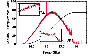
Fig 1: Spectral Function and integral for Matched HOM Coupler and 2Kn/f (Shown Dashed)
The spectral function method has so
far been employed principally to explore the effect of manifold
mismatch on the DDS wake function. We begin with the spectral
function for the matched manifold case, shown in Fig. 1. We have
shown the smoothed spectral function, 2Kn![]() n/
n/![]() f, for the undamped
case (ie the G set equal to zero case) on the same curve. (The
unsmoothed spectral function, 2Kndn/df, is a sum of delta
functions as noted before.) One sees that the effect of the damping
is to replace the delta functions by broadened peaks which produce
an oscillation about the smoothed umdamped spectral function.
The wake envelope function for the matched DDS structure and,
for comparison, the corresponding function for the NLCTA DT structure
are shown in [5]. There the recoherance peak of the DT is seen
to be strongly suppressed by the damping.
f, for the undamped
case (ie the G set equal to zero case) on the same curve. (The
unsmoothed spectral function, 2Kndn/df, is a sum of delta
functions as noted before.) One sees that the effect of the damping
is to replace the delta functions by broadened peaks which produce
an oscillation about the smoothed umdamped spectral function.
The wake envelope function for the matched DDS structure and,
for comparison, the corresponding function for the NLCTA DT structure
are shown in [5]. There the recoherance peak of the DT is seen
to be strongly suppressed by the damping.

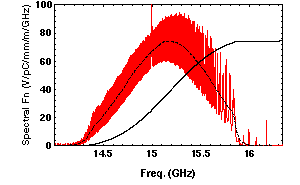
Fig 2: Spectral Function For Fabricated
DDS and its Integral
A series of investigations demonstrated
that the wake function was seriously degraded by small mismatches
of the manifolds, especially on the output (hence downtapered)
side. Accordingly a major effort was made to design mitered bend
type structures to match the manifolds to standard waveguide
(WR62 was used). The results achieved for both the input and
output side are given in [4]. In order to test the structure
in the ASSET experiment it is necessary to attach windows and
loads. The available windows were unfortunately not well-matched
in the 14 to 16 GHz band that is crucial to the damping. The
window and manifold added

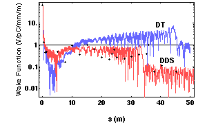
Figure 3: Wake Function for Fabricated
DDS, ASSET data for DDS and NLCTA DT (Copper Losses Shown Dashed)
in quadrature are also illustrated in
[6]. The combined reflection coefficient for the output end of
the manifold has a minimum of .09 at 15.05 GHz rising to .37 at
14.2 and .4 at 16. Ghz. At the input end the reflection coefficients
are similar in the upper half of the frequency range but less
than .09 for the lower half.
The effect of these reflections on the
spectral function and wake envelope function are shown in Figs.
2 and 3. As compared to the matched case the oscillations of
the spectral function show a large increase in amplitude, indicating
significantly higher Qs for many of the modes, and the wake envelope
function is substantially degraded. However, even with the degradation
shown in Fig. 3, the results constitute a considerable improvement
over the DT structure. Preliminary ASSET experimental results
have already been obtained [7], and the experimental points have
been superposed on the Fig. 3 curve. Matched windows over the
required band are in preparation, and simulations already performed
[4] indicate a two-fold improvement in the wake function over
that of the present structure.
The DDS described here was designed
with rather crude theoretical tools [2]. However, the well-founded
theoretical analysis given here and in [1] were carried out after
the design was complete (but prior to fabrication). While the
agreement between the preliminary experimental results and the
theoretical predictions is imperfect, given the differences (some
planned, some inadvertant) between the theoretical design and
the structure as fabricated, the comparison suggests that the
present version of the theory provides both the physical insight
and the quantitative analysis needed to design an improved structure,
and a number of such improvements are under consideration [4].
This work is supported by DOE grant number DE-FG03-93ER40759‡ and DE-AC03-76SF00515†. We have benefited greatly from discussions at the weekly structures meeting at SLAC, where these results were first presented and thank all members of the group.
[1] R.M. Jones, et al, Equivalent Circuit Analysis of The SLAC Damped Detuned Structure, SLAC-PUB-7187, EPAC96 Proc.
[2] K. Ko, et al, Design Parameters for the Damped Detuned Accelerating Structure, SLAC-PUB-95-6844, PAC95 Proc.
[3] K. Bane and R. Gluckstern, Particle Accls.,42, p 123 (1993).
[4] R.M. Jones et al, 1996, To be submitted, Phys, Rev E.
[5] R.H. Miller, et al, A Damped Detuned Structure for the
Next Linear Collider. Paper Thp02 in this conference.
[6] M. Seidel, et al, Microwave Analysis of the Damped Detuned Structure. Paper Thp05 in this conference.
[7] C. Adolphson, et al, Aug. '96, private communication.