†Stanford Linear Accelerator Center, M/S 26, P.O
Box 4349, Stanford, CA 94309
‡University of California, San Diego, La Jolla, CA
92093-0319.
¥KEK, National Laboratory for High Energy Physics,
1-1 Oho, Tsukuba-shi, Ibaraki-ken 305, Japan
*Univ of Maryland, College Park, MD 20903
An X-band Damped Detuned Structure (DDS) for NLC has been fabricated as part of a collaboration between KEK and SLAC. The individual cells were diamond point machined and microwave tested at KEK. The cells were diffusion bonded at SLAC. The structure has been cold tested. The time dependence of the beam induced dipole wakefields have been measured with the SLC beam in the test station ASSET. The structure is designed so that the dipole modes have an approximately gaussian density distribution in the frequency domain. This gives an approximately gaussian decrease of the wakefields for short times (about 10 ns), which is produced by the interference among the 206 modes in the lowest dipole mode band of the 206 cell structure. Without damping, however, the wakefields then rise back to a level which is approximately equal to the expected incoherent level from the 206 modes. The damping is accomplished by means of 4 rectangular slots or manifolds (approximately 5 mm by 10 mm) equally spaced in azimuth around the structure and running the full length of the structure. These manifolds act as single mode rectangular waveguides for the lowest band dipole modes, but are cut off for the accelerating mode. The manifolds are coupled to every cell in the structure, except for 3 at each end, by means of radial slots. Each of the four manifolds will have the dipole mode frequencies traveling in both directions and so are terminated on both ends. The structure will be installed in the NLC Test Accelerator this fall.
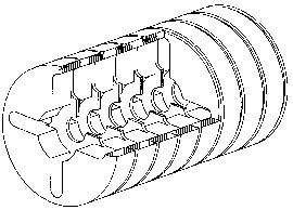
Although the Damped Detuned Accelerator Structure, Fig 1, is being developed for the SLAC design of the Next Linear Collider, the concept is applicable to any long pulse, high pulse current accelerator. Indeed when linear collider designs go to many bunches to improve luminosity, they face the same problem which limits the performance of many industrial accelerators, linacs used for particle physics and linacs proposed for driving high power FEL's: long range dipole wakefields distort the particle orbits causing transverse emittance growth and eventually Beam Break Up. The structure discussed here achieves 2 orders of magnitude reduction in the transverse wakefields and may be capable with some modifications of as much as 3 orders of magnitude suppression. Thus the approach of detuning structures for short range wakefield suppression combined with light damping using manifolds may be an important innovation in the design of linacs.

One of the important features of DDS's is that any dipole modes which the beam excites propagate through the manifolds to the end of the structure. Since the structure is detuned, there is a one to one relationship between the dipole frequency excited and the longitudinal position in the structure where the beam excited the mode. Thus, the spectrum of the dipole signals observed in the manifolds provides an internal monitor of the beam position relative to the structure, with a longitudinal resolution which can be a small fraction of the structure length. For the structure discussed here the resolution is of the order of 10 cells in the 206 cell structure.
The manifold damping used in the DDS works only because the structure is detuned. If the accelerator was a uniform (constant impedance) structure the beam would interact with a single velocity of light dipole mode which would not couple to a simple waveguide manifold where the phase velocity is necessarily greater than the velocity of light. A coaxial manifold would couple to the dipole mode, but it would be difficult, perhaps impossible, to keep it from coupling to, and therefore damping, the fundamental accelerating mode. In the detuned structure, all the dipole modes which interact with a velocity of light beam also have a region where the phase velocity is greater than c and equal to the phase velocity for their frequency in the damping manifold. In this region (different for each mode), where each dipole mode in the accelerator cells is synchronous with the mode in the manifold, the coupling takes place. A synchronous condition must be met because there is a coupling hole between each manifold and every cell in the accelerator. Thus, in effect, there is a multihole coupler between each manifold and the accelerator. Since each dipole mode has a different frequency, each mode is synchronous with the manifold and hence couples to it in a different longitudinal region of the accelerator. Since the manifolds are simple rectangular waveguides they are not synchronous with the fundamental accelerating mode anywhere, and, indeed, they are cut off for the accelerating frequency.
The pressure of the schedule for testing the structure for wakefield
in the ASSET facility [1] in SLC and for installation in NLCTA
forced the parameters of the first DDS to be frozen before an
adequate theory existed to analyze its performance. As a consequence
the performance of this first structure is degraded, but it can
be significantly improved by some fine tuning of the design.
Gaussian Detuning. The goal of the gaussian detuning is
to create a dipole impedance which is approximately a gaussian
function of frequency, so that the wakefields will decay in an
approximately gaussian manner. However, since it is a complicated
calculation to get from the tapered structure parameters, or from
equivalent circuit parameters to the functional dependence of
the impedance on frequency, how does one get started? The solution
is to make the quasi-uncoupled approximation: that after excitation
by a velocity of light delta function bunch each cavity rings
not at its resonant frequency, but at the velocity of light synchronous
frequency of a periodic structure of that cavity. The justification
for this approximation is that the boundary values for the fields
in each cell are the fields in the adjacent cells which were excited
by the same velocity of light bunch. Detailed equivalent circuit
analysis by Bane and Gluckstern [2] indicates that this is a very
good approximation. For the present structure the cells were picked
to have gaussian density distribution of the synchronous frequencies.
It would have been slightly better to have Kn (dn/df)
be a gaussian function of the synchronous frequency, where Kn
is the kick factor (=1/4 ![]() R/Q) of the nth cell. The gaussian width
factor
R/Q) of the nth cell. The gaussian width
factor ![]() =2.5%, and the gaussian is truncated at +/-2
=2.5%, and the gaussian is truncated at +/-2![]() .
.
Single Mode Manifolds. Although multimode manifolds were studied first, the final design utilizes single mode manifolds. Each design has advantages and disadvantages, and the choice is not clear cut. The multimode manifold was rejected for two reasons: concern about a fragile thin iris between the manifold and the cell and complexity of analysis of cell to manifold coupling in five modes. The single mode design chosen has no iris because the hole between the manifold and the cell is as wide as the manifold (the small dimension of the rectangular waveguide) and as long as the cell.
Advantages of Single Mode Manifold:
1) Smaller, and well cut off for Accelerator frequency
2) Easier to couple out at ends since it is single mode
3) Simpler to fabricate - no thin iris
4) Perhaps easier to analyze - fewer modes
5) Negligible degradation of accelerator shunt impedance
Disadvantages of Single Mode Manifold:
1) Match of terminations quite critical
2) Over coupling perturbs mode structures, frequencies and Q's introducing deleterious fluctuations in the gaussian impedance function
3) The single mode manifold chosen here couples only to the TE component in the dipole mode, which gets very small at the output (high dipole frequency) end of the structure. This makes it difficult to get adequate coupling. A narrow radial slot running from each manifold part way into the disk can raise the coupling and solve this problem.
4) Lower conductance for vacuum pumping
With careful design it should be possible to overcome satisfactorily
the first 3 disadvantages, so the single mode design remains our
design of choice.
Choice of Q. For the present structure Q of 1000 was chosen as the target value for all the lowest band dipole modes which interact strongly with the beam. This was chosen to attenuate the wakefields by a factor of e by 20 ns after the excitation, the time at which the wakefield envelope is rising again from the renewed constructive interference of the modes on the edges of the gaussian. However, the Q of 1000 corresponds to a resonance width, f/Q, twice as large as the mode separation at the peak of the mode spectrum, which produces mode distortion in the single mode design. In a multimode design, each waveguide mode would have weaker coupling and since each would couple power out of the mode at a somewhat different location, there would less mode distortion for the same loaded Q.
A better approach to the choice of Q and hence of the required
coupling to the manifold, results from realizing that the motivation
for the damping is to produce a dipole impedance which is a smooth,
approximately gaussian, function of frequency. Thus we would like
the width of the nth resonance to be fn/Qn
= kdfn, where k is a constant close to 1, and ![]() fn
is the mode spacing in the vicinity of the nth mode. The value
of k should be chosen to give the smoothest impedance as a function
of frequency. The optimum k would probably be higher for a multimode
design.
fn
is the mode spacing in the vicinity of the nth mode. The value
of k should be chosen to give the smoothest impedance as a function
of frequency. The optimum k would probably be higher for a multimode
design.
The manifold coupling and hence the Q's are controlled in the
present design primarily by varying the distance between the manifold
and the accelerator cells and thus the length of the hole between
them. The secondary method of varying the coupling is to vary
the cutoff frequency, fc, of the manifolds. This affects
the coupling because the dipole modes in the accelerator have
a large TE component at small phase advance per cell and a small
TE component at large phase advance. The manifolds couple only
to the TE component of dipole modes because the narrow walls of
the rectangular manifolds are adjacent to the outer surface the
accelerator cells. In the TE10 mode the magnetic field along the
narrow wall of the manifold is longitudinal and consequently does
not couple to a TM mode in the cell. The higher the cutoff frequency
of the manifold, the smaller the phase advance at the avoided
crossing where the manifold couples to a particular cell, and
hence the stronger the coupling. The cutoff frequency, fc,
varies from 12.5 GHz at the input end to 14.0 Ghz at the output
end in order to increase the coupling at the output end.
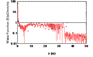
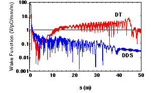
Since the equivalent circuit analysis is the subject of another paper at this conference [3], only some of the most important results will be presented here. Fig 2 compares the wakefields for the Detuned structure (DT) with no damping but including the copper losses and the DDS with perfectly matched terminations each calculated with the equivalent circuit analysis.. Fig 3 presents the calculation for the DDS structure with the existing terminations. The round dots are the preliminary data from the measurements of the wakefield of the DDS using the SLC beams in ASSET [4].

Prior to and during the design of the output structure for the manifolds, an equivalent circuit investigation of the effect of manifold mismatch on the wake function was carried out. It was found that while the wake function was relatively insensitive to small reflections at the input end, even very small reflections at the output end produced significant degradation. This asymmetry is presumed to be related to the fact that the field patterns of the exact damped eigenmodes with matched termination show a strong asymmetry in manifold excitation, favoring the output end. While this effect is not yet understood, it is absent in the manifold excitation patterns given by perturbation theory and hence must be a consequence of pattern distortion associated with strong coupling. The ASSET tests show nine times as much energy emerging from the output end of the manifolds as compared to their input end, a circumstance which is presumably a reflection of these phenomena. An equivalent circuit theory for these spectra had been worked out in anticipation of the ASSET tests, but it has not yet been implemented.

As is suggested by comparison of Figs. 2 and 3, the termination match at present is not very good: a VSWR of about 2 at the band edges at 14.2 and 15.8 GHz and dropping to about 1.2 at the center of the band, 15 GHz. At all 8 terminations (both ends of 4 manifolds) the dominant mismatch above 15 GHz is due to the windows, which are replaceable. Better windows are presently being developed, which we anticipate will be 1.1 or better over the full range. At 14.2 GHz the problem exists only at the output end, where we were unable to design a mitered bend from the manifold waveguide with a cutoff at 14.0 GHz which had a good match from 14.2 GHz to 15.8 GHz. Since the manifold and the mitered bend are integral parts of the accelerator, the remedy must await the next structure. We intend to adjust the taper of the manifold dimensions so that fc is about 13.5 GHz at the mitered bend.
There is an optimum coupling strength as a function of frequency which gives the smoothest impedance function. If the coupling is too strong it produces striking fluctuations in the amplitude of the kick factor, the Q's and in the mode density which all can give deleterious fluctuations in the impedance function.
This work is supported by DOE grant number DE-FG03-93ER40759‡ and DE-AC03-76SF00515†.
[1] C. Adolphsen, et al, Measurement of Wakefield Suppression in a Detuned X-band Accelerator Structure, LINAC94 Proc., p 481.
[2] K.L.F. Bane and R.L. Gluckstern, Part. Accel.,42,p 123 (1993).
[3] R.M. Jones, et al, A Spectral Method Applied to the Calculation of the Wake Function for the NLCTA, Paper THP04 this conference.
[4] C. Adolphsen, et al, paper in preparation.