Institute for Theoretical and Experimental
Physics (ITEP)
B.Cheremushkinskaya 25, 117259, Moscow, Russia
Two new mutually supporting ideas to overcome problems resulting from inevitable particles loses in ADTT linac and significantly improve reliability of its operation are discussed. To decrease induced radioactivity it is proposed to insert into linac channel material with extremely low activation cross-section and to use in main part of the linac single - gap cavities (room-temperature or SC) supplied by individual force phased low power generators. Realization of these proposals allows to overcome strong physical limitations on beam losses and to reach non-stop operation of the linac in spite of failures in one or several channels of the high-beta linac part.
The significant and rising interest to new technologies on processing of nuclear wastes, use of weapon-grade plutonium, production of nuclear materials (3H and 239Pu), and also a thorium fuel cycle development, stimulate design of 1 GeV high-current accelerators. These accelerators, as major part of electronuclear installations, are considered in different variants both proton linacs [1,2] and cyclotron complexes [3]. Beam current varies typically from 10 up to 100 mA depending on application.
Main problems under design of the high-current linac are achievement of minimum activation of its parts and long time non-stop operation. The activation level, determined by high-energy proton losses should permit hand-on maintenance of the machine.
Studies of beam halo formation as main reason of particles losses are conducted in many scientific centers of the world [4,5]. Unfortunately, despite of plenty interesting results, there is no reliable method of an estimation of small particles losses, which define actual linac activation. Our approach is based on the LAMPF beam losses data. The losses are about 0.2 nA/m at average beam current of 1 mA. We accept this beam losses level as a limit, which allows hand-on maintenance of the machine. On the basis of published results, it is difficult to assume reduction of relative losses with increasing of average current up to 100 mA. Thus, the enough quick achievement of radiation-free condition becomes very problematic.
As it is mentioned above, the second major problem of designing of high-current linac is to ensure non-stop operation of the electronuclear complex. In existing linacs uninterrupted operation depends mainly on a reliability of RF system. In our proposal the linac operation reliability does not practically depend on failure one or several RF generators and resonators of main part of the accelerator (MPA).
Supposed new ideas are the use of materials with low activation and small yield of neutrons for accelerating structures manufacture as well as application of single-gap resonators with individual RF supply and external phasing of accelerating fields for MPA.
In majority of the projects RFQ structure is accepted as initial part, DTL structures with arrangement of quadrupoles in drift tubes or outside of resonators (BCDTL, CCDTL etc.) are considered as the intermediate part. The 700 - 1000 MHz CCL and DAW are usually considered as MPA. However appreciable distortion of an accelerating field in CCL cells can make inconvenient of its use for acceleration of high average current beams [6]. Main lacks of DAW are relative complexity of manufacturing and tuning but also difficulty of heat remove at high average power.
Use of RF generators of high unit power (about 1 MW) in all earlier proposed projects influences on choice of length and type of focusing structure in MPA, that results in serious difficulties at feeding of high CW power in resonators and stops the operation of whole machine at failure of even one generator.
In Fig.1 the linac block-scheme is presented, in which specified proposals are introduced. The accelerator consists of injector, RFQ section, Alvarez type DTL as intermediate part and main part, consisting of 2300 single-gap resonators disposed in groups of 3 to 6 ones between focusing quadrupoles. The main parameters of the accelerator are presented in Table.
RFQ with coupling windows (4-ladder type) is used in the proposal [7]. RFQ is terminated by output dynamic matcher developed according to [8].The DTL is Alvarez-type accelerating structure with PMQ's. An opportunity of use PMQ in DTL-section of CW linac is provided due to application of low activation and small neutron yield graphite absorbers in an area of drift tubes apertures. The absorber thickness is chosen by constructive reasons, ensuring absorption more than 99 % of lost particles. The minimum thickness changes from 0.1 mm at 5 MeV up to 2 mm at 100 MeV.
The accelerating module at the beginning of MPA is
schematically shown in Fig.2. The MPA consists of single-gap toroidal
resonators groups between which magnetic quadrupoles are placed.
The resonators are made of graphite. Their internal surface is
covered by 0.1 mm Cu-layer, that provides necessary electrical
conductivity and improves vacuum conditions. The number of resonators
in each group is equal to 3 at the beginning and to 6 at the MPA
end. MPA focusing period length is 8
![]()
![]() .
The ion line elements inside
lenses are graphite tubes, the wall thickness of which gradually
grows from 2 up to 20 mm.
.
The ion line elements inside
lenses are graphite tubes, the wall thickness of which gradually
grows from 2 up to 20 mm.
The main advantage of MPA consisting of single-gap resonators is that of linac saves operation condition even at failure of several successive resonators. Even without acceptance of special measures in case of absence for any reasons of acceleration in any of resonators the beam remains stable in subsequent steps of acceleration. Thus arising output energy oscillations do not disrupt operation of target blanket complex even at presence of bend magnets in the extraction and beam distribution channel. Independent excitation of each resonator permits by means of control system to remove energy variations and longitudinal coherent particle oscillations due to change of RF field phase (and/or amplitudes), at which the beam passes accelerating gaps, following by faulty one.
Calculations show, that MPA based on 600 MHz toroidal single-gap resonators is on a par with CCL and DAW by such parameters as an effective shunt-impedance. In contrast to multi-gaps resonators there are no problems, connected with tuning and stabilization of accelerating fields in the single-gap resonator. In particular, it means, that the requirements to accuracy of manufacturing of single-gap resonators are much reduced in comparison with multi-gaps ones. Whole MPA can be constructed by using of 3-4 types of toroidal resonators, a fact that makes MPA cheaper in manufacturing. The independent phasing permits to decrease distance between gaps and reduce 20-50 % MPA length.
To excite single-gap resonators, 55 kW (for 100 mA CW beam current) RF generators are required which can be located near the resonators. Such level of RF power for resonators supply does not represent difficulties and does not require application complex and expensive feeder system. Use of single-gap resonators permits in the best way to realize idea of application of materials for lost particles absorption. Estimations, showing an opportunity of manufacturing of the MPA resonator completely from the similar material are done. For example, use fine-grain pyrolytic graphite having significant mechanical durability, high heat conductivity and ability to form with copper strong connection, permits to create the resonator for CW mode operation with characteristics are on a par with resonators constructed from usual materials, but almost without of induced activation.
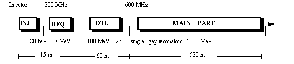
Fig. 1 A Block - scheme of the 1000 MeV Linac with output beam current 10 - 100 mA
An important additional feature of our MPA scheme is a fact that
the distance between neighbouring gaps practically does not depend
on ![]()
![]() due to opportunity to force required phase that allows MPA
length reduce to 530 m.
due to opportunity to force required phase that allows MPA
length reduce to 530 m.
The given scheme and presented proposals allow to realize linac both for CW at average beam current 100 mA, and for pulsing mode at average current 10 mA (pulse current 100 mA). At identical accelerating structure designs they differ only by RF system power.
The realization of the considered above proposals on design of high-current linac allows to overcome physical restriction on value of particle losses, representing main obstacle to increase of beam intensity from 1 mA up to 100 mA. Elimination of reliability dependence of the whole electronuclear complex on linac RF system reliability permits easily to reach a high level of non-stop failure operation. The basic advantages of the given scheme are as follows:
| Parameter | |||
| Structure Type | |||
| Energy (MeV) | |||
| Frequency (MHz) | |||
| Number of cavities | |||
| Total Length (m) | |||
| Aperture Bore Radius (cm) | |||
| Average Field (MV/m) | |||
| Synchronous Phase (deg) | |||
| Shunt Impedance (eff.) (M | |||
| RF power losses in wall (MW) | |||
| Beam Power (for 100 / 10 mA) (MW) | |||
| Number of RF Generators | |||
| Efficiency of Resonators (%) | |||
| Quadrupole Lattice | |||
| Quadrupoles Gradient (T/m) |
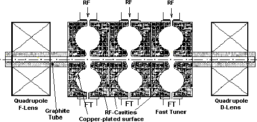
Fig. 2 B Schematic view of MPA resonators