An electron linear accelerator has been constructed as an injector of a 300 MeV electron storage ring (Kaken Storage Ring, KSR) at Institute for Chemical Research, Kyoto University. The output beam energy of the linac is 100 MeV and the designed beam current is 100 mA at the 1 msec long pulse mode.
The transverse and longitudinal emittance are measured
to evaluate the beam quality for the beam injection into the KSR.
They are observed by the profile monitors combined with quadrupole
magnets or an RF accelerator. The results are that the normalized
transverse emittance is 120 p.mm.mrad.
The longitudinal emittance is 15 p.deg.MeV
and the energy spread is +2.2 %.
A compact electron storage ring (Kaken Storage Ring, KSR) is now under construction at the Institute for Chemical Research, Kyoto University [1]. The layout of the accelerators is shown in Fig. 1. The KSR has a race track shape and its maximum beam energy is 300 MeV. It will be used as the synchrotron radiation source from the dipole magnet and the insertion device. The critical wave length of the synchrotron radiation is 17 nm. It will be also used for the research of the free electron laser.

Table 1 Beam parameters and main specifications of the linac.
| Output Electron Beam | |
| Energy | 100 MeV |
| Max. Pulse Width | 1 msec |
| Max. Repetition | 20 Hz |
| Electron Gun | |
| Cathode Assembly | Y-796 (Eimac) |
| Max. Extraction Voltage | -100 kV DC |
| Accelerating Structure | |
| Bore Radius | 11.74 - 13.4 mm |
| Length | 3 m |
| Operating Frequency | 2857 MHz |
| Maximum Electric Field | 15 MV/m at 20 MW |
The construction of the linac had been finished and
we succeeded to accelerate the electron beam of 140 mA in October,
1995. The design beam energy is 100 MeV and the pulse width is
variable from 10 nsec to 1 msec.
Table 1 shows the main linac parameters. The linac will be also
used for the experiments of the coherent X-ray generation by the
election beam. Especially, the parametric X-ray radiation (PXR)
experiment has been already started.
The electron gun has the Pierce electrode and the cathode assembly is the Y-796 (Eimac). The maximum extraction voltage is -100 kV. The pre-buncher is a single reentrant cavity. It is designed to bunch the beam within the phase spread of 60 degree. The buncher is a disc-loaded and 3 step constant gradient structure. It has 21 cells and the total length is 777 mm. The designed phase spread is within 3 degrees at the beam current of 100 mA when the input power is 12 MW.
There are three main accelerating structures. The
main characteristics of the accelerating structure are also listed
in table 1. The maximum electric field is 45 MV per an accelerating
structure without beam loading at the input power of 20 MW.
The doublets of the quadrupole magnets are used as focusing
elements between the accelerating structures.
There is a klystron for each accelerating structure.
The total number of the klystron is 4 including the buncher, pre-buncher
system. The klystron is ITT-8568. The maximum output power is
21 MW and the pulse width is 2 msec.
We are going to replace the klystron with Mitsubishi PV3030A2.
The present modulators and the focusing coils are reused for the
new klystrons so that the replacement cost and time can become
minimum. The solenoid is a single electromagnetic coil and generates
the magnetic field of 0.9 kGauss on the axis. Figure 2 shows the
relation between the cathode voltage and the output power. The
output power of 30 MW is available at the cathode voltage of 250
kV. The power efficiency is 48 %.

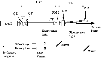
The beam emittance and the energy is measured downstream
of the linac. Figure 3 shows the schematic view of the beam monitor
section. The beam current is measured by the current transformer
(CT) with ferrite core. The main components in this section are
two profile monitors (PM1, PM2). They consist of screens, CCD
cameras and an image memory unit. The image data is analyzed by
the computer in the control room. The material of the fluorescence
screen is an alumina ceramic in which a little chromium oxide
is homogeneously doped (Desmarquest, AF995R). PM1 is used for
the measurement of the transverse beam profile and the emittance.
PM2 is used for the measurement of the energy spread and the longitudinal
emittance.
Transverse Beam Profile and Emittance
The shape of the beam distribution in the transverse phase space is assumed,
, (1)
where a, b, g are Twiss parameters and e is the transverse emittance. The Twiss parameters are transformed from QD to PM1according to the following equation.

(2)
where m.. are elements of a transfer matrix between QD and PM1.
(3)
From the formula (2), the rms beam radius s at PM1 is obtained.
(4)
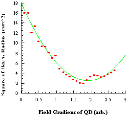
where the Twiss parameters are values at QD. We measure the beam size by the profile monitor (PM1) with various field gradient of QD and calculate the emittance by the least square fitting.
Figure 4 shows the relation between sPM12 and the field gradient of QD. The beam current is 100 mA and the pulse width is 100 nsec. It is the operation mode of the beam injection into the KSR. The unnormalized emittance at QD is 0.57 p.mm.mrad and the normalized value is 120 p.mm.mrad.

Figure 3 Schematic view of the beam monitor section
down-stream of the linac.
Acc3:Third accelerating structure, CT:Current transformer,
QD,QF:Quadrupole magnets, PM1,PM2:Profile monitors,
AM:Analyzing magnet.
Energy Spread and Longitudinal Emittance
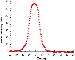
The beam energy spread is measured by the profile monitor (PM2) downstream of the 5 degree analyzing magnet. The rms beam radius s at PM2 is,
(5)
where h is the dispersion and is 0.15 m. The first term is due to the transverse emittance and it is calculated from the measured data. The second one due to the energy spread. The correlation is assumed to be negligible between the two terms. The measured beam profile at PM2 is shown in Fig 5. The beam current is 100 mA and the pulse width is 100 nsec. The center beam energy is 109 MeV and the energy spread is +2.2 %.

Figure 4 Relation of the square of the rms beam radius
and the field of the quadrupole magnet (QD). The solid line shows
a best fit curve.


To observe the longitudinal emittance, the phase of the last accelerating structure (Acc3) is set so that the relativistic electron beam go through it with the synchronous phase of zero. The transfer matrix from Acc3 to PM2 is,
(6)
where q and E are relative phase and energy to the synchronous particle. In this formula, the approximation is used because the synchronous phase is zero.
(7)
Similar to the formula (4), the relation of the rms energy spread, longitudinal emittance and Twiss parameters is,
(8)
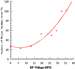
The energy spread is measured with various RF voltage (Vrf) and the longitudinal emittance is calculated by the least square fitting.
Figure 6 shows the relation between the square of
rms beam radius at PM1 and the RF voltage of Acc3. The beam current
is 100 mA and the pulse width is 100 nsec. The center beam energy
is 71 MeV. The longitudinal emittance is 15 p.deg.MeV.
The phase spread is +8.0 degree.
[1] A.Noda, et al., "Electron Storage Ring, KSR for Light Source with Synchrotron Radiation" , Proc. of the Particle Accelerator Conference, Dallas, USA, 278 (1995)
[2] T.Shirai, et al., "A 100 MeV Injector for the Electron Storage Ring at Kyoto University" , Proc. of the Particle Accelerator Conference, Dallas, USA, 1079 (1995)
[3] N.Sereno, et al., "Bunch Length Measurements at the Advanced Photon Source (APS) Linear Accelerator" , Proc. of the Particle Accelerator Conference, Dallas, USA, 1070 (1995)
[4] Y.Bylinsky, et al., "Longitudinal Emittance
Measurement of the 100 MeV Proton beam" , Proc. of the Particle
Accelerator Conference, San Francisco, USA, 3062 (1991)