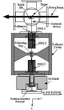
We measured the longitudinal phase space distribution of the proton beams provided by the 433 MHz linac at ICR, Kyoto University, by means of a new monitor which consists mainly of a thin gold target, a deflector cavity, a position sensitive detector (PSD) and three permanent magnet quadrupole lenses. Protons are scattered by the target are guided into cavity, then focused by the PMQs, deflected by the cavity, then focused by the deflector electrodes, and finally reach the PSD. The position and energy data from the PSD are employed to reconstruct the phase space configuration of the beam before hitting the target. The longitudinal emittance of the ICR linac was measured with the present monitor system under some different operating conditions. The obtained measurement results were used to optimize the RF condition.
At the Institute for Chemical Research, Kyoto University, a 433 MHz proton linac has been operated. The linac mainly consists of 50 keV Ion source, and low energy beam transport, 2 MeV Radio Frequency Quadrupole (RFQ) linac, Beam Matching Section (BMS), and 7 MeV Drift Tube Linac (DTL)[1]. In order to measure the longitudinal beam emittance of the 7 MeV proton beam, we developed a new beam monitor [2]. The monitor enables us to measure the beam distribution in the longitudinal beam phase space.
The longitudinal beam distribution of the proton linac is obtained by measuring the position and energy of the protons which are scattered at the target and then deflected by an rf field whose frequency is the same as those of RFQ linac and DTL. The figure of the longitudinal emittance monitor is shown in Fig.1.
The position and energy of a proton measured by Position Sensitive Detector (PSD) depend on the phase and energy when it is scattered at the target. By calculating the orbit of the deflected proton, the coordinates of the proton in the phase space can be obtained. In this way, a beam distribution in the longitudinal phase space is reconstructed from the measured position and energy distribution.
When we accelerate the proton beams, how we control
the rf condition is large problem. Then the variations of the
longitudinal beam distribution at different rf conditions were
measured, in order to examine the effect of the rf condition to
the longitudinal beam dynamics.
We measured the beam distributions for several rf conditions. In the measurement, we used a gold target of 0.37 mm in width and 100 mg/cm2 in thickness. The gold is deposited on a thin carbon backing foil whose thickness is 10 mg/cm2 . The gap voltage of the deflector is 38 keV estimated from the position variation of the deflected protons when the rf phase of the deflector is changed.
The longitudinal beam matching was controlled by adjusting the rf phases and amplitude of the RFQ, the DTL and a double gapped buncher installed in the BMS.
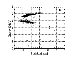
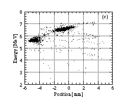
Some of the results are shown in Fig. 2(a)-(d). The four figures are beam distributions on the PSD. We can find two islands on each figure; the upper island comes from the protons scattered by gold target, and the lower island comes from those scattered by carbon foil. The longitudinal emittances can be estimated from the upper island.
Fig. 2(a)-(d) correspond to following conditions A - D. The condition A is well matched rf condition, and the shape of the upper island is well-regulated. In the condition B, the rf phase of the DTL is different from that of A by 11_. The shape of the upper island become a little deformed, and the mean output energy is less than A, and protons out of stability region are more than A. In the condition C, the rf is miss matching, where the rf phase of the DTL is different from that of A by 43_ . Many unstable protons are found. In the condition D, the buncher voltage was made zero, and the rf conditions of RFQ and DTL were optimized. The spread of the detected positions is larger than that for other conditions. Because the RFQ output beam was not rebunched, not some amount of protons may go out of acceptance of the DTL.
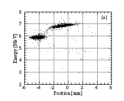
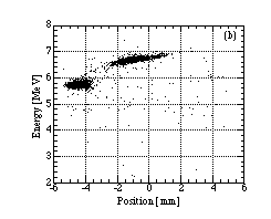
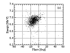
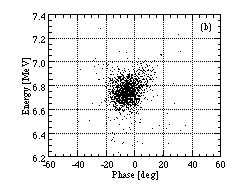
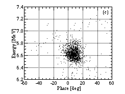
The position-energy distribution of the scattered
proton are transformed to longitudinal phase space distribution.
From the distributions of the upper proton islands of Fig. 2(a)-(c),
the phase space distributions are obtained, as shown in Fig. 3(a)-(c).
It is difficult to transform the distribution in Fig. 2(d), because
the beam spread is too large. The phase center of distribution
are varied, and mean energies of (b) and (c) are lower than (a).
We estimated the effective rms emittance, considering the effects
of measurement resolutions, by using following formula [3],
where sf is resolution of the phase measurement, and sE is that of energy measurement. In this measurement sf is 4.5 deg, and sE is 14 keV. In order to get high phase resolution, we used a narrower target than previous experiment, but this was not so effective. Only the change of setting angle of the target as shown in Fig. 1 might be effective to the phase resolution.
We calculated two kinds of rms emittances. One is
calculated from all particles, and the other is calculated from
the particles in a window of 50 deg ¥
600 keV . The purpose of the window is to
estimate the rms emittance of stable beam. The obtained rms emittances
for each distributions are shown in Table 1. The size of rms emittance
for condition A and B are almost same, but the emittance (all)
for C is 1.4 times as large as that for A.
|
| |
Longitudinal rms emittances of the beams for different
rf conditions. The rms emittances in the window are calculated
from the particles in a area of 50 deg ¥
600 keV around the center .
We measured the longitudinal beam distribution at
the different rf conditions. The distributions were different
by the condition, and we got the optimizing rf condition with
this measurement. Then longitudinal rms emittances are obtained
for three conditions. At a large mismatched phase, the rms emittance
found to be 1.4 times larger than that of matched beam.
[1] Y. Iwashita, M. Inoue, H.
Ego, H. Okamoto, S. Kakigi, M. Sawamura, T. Shirai, H. Fujita,
K. Fukunaga, and H. Takekoshi , Bull. Inst. Chem. Res., Kyoto
Univ. 68, 156 (1990)
[2] H.Dewa, H. Ao, T.Kihara, H. Tonguu, T. Shirai,
H. Okamoto, Y. Iwashita, H.Fujita, S. Kakigi, A.Noda and M. Inoue
ìLongitudinal beam emittance monitor for 433 MHz proton
linacî, Review of Scientific Instruments (to be published)
[3] V. W. Yuan, R. C. Connolly, R. C. Garcia, K. F. Johnson, K. Saadatmand, O. R. Sander, D. P. Sandoval and M. A. Shinas, Nucl. Instrum. Methods.A 329, 381, (1993)