A Three Dimensional Bunch Shape Monitor (3D-BSM)
has been developed for the CERN Proton Linac 2. A new area for
beam studies at high intensities has been opened by this detector.
Bunch density distributions in all three dimensions and their
variations along the beam pulse can be obtained. Changing field
gradients in linac quadrupoles, emittance variation along the
bunch has been calculated. Measurements of beam halos become possible
thanks to the large dynamic range of the device. Beam parameters
at various linac settings have been measured and analysed.
The new detector [1] allows the measurement of the
three dimensional density distribution I(x,y,z) of a bunch and
its evolution along the beam pulse. For example, using this distribution
the first and second moments and the beam profiles in each direction
(x,y,z) have been obtained. The CERN Linac 2 is a high intensity
accelerator consisting of an RFQ and three Alvarez tanks producing
140 mA of protons at 50 MeV [2]. As proven during the detector
commissioning, the 100 m tungsten wire can operate safely with
pulse lengths up to 145 s. The insertion of the target in the
beam does not disturb injection into the downstream booster synchrotron.
Therefore the 3D-BSM can be used as a non-destructive beam diagnostic
tool during linac operation.
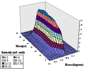
In Fig.1 the evolution of the longitudinal profile
along the beam pulse is presented. The analysis of the figure
as well as of the evolution of other beam parameters along the
bunch shows that beam-loading is well compensated in Linac 2.
There is no variation either of the bunch centre or the bunch
shape along the entire pulse length. It has been demonstrated
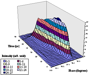
that the bunch shape changes along the pulse if beam-loading is
not sufficiently compensated. This can be seen in Fig. 2 where
the RF field in tank 3 has been increased by 4% while keeping
the maximum power to the tank constant.
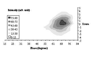
When changing the phase of tank 3 in a 60 range, the bunch length varies between 13 and 30 (1 rms values) and the phase of the bunch centre (with respect to the phase of the reference line) varies by 130 (see Fig. 3). Deviation of the bunch centre phase is due to two main reasons: the energy change and the coherent oscillations in the longitudinal phase space.
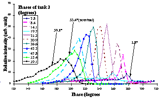
Although the present phase setting of the last tank (53.4) produces long bunches with a specific tail (see Fig. 3), it seems that the energy spread is moderate in that case, so that the beam is safely transported to the booster rings.
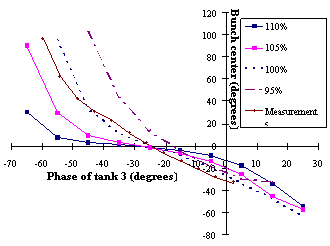
The high intensity beam dynamics for different phases
of tank 3 have been simulated by the computer code LANA [3]. Simulations
gave a bunch width about two times smaller than the observed one.
The difference is mainly due to the tails. The central part of
the bunch is well reproduced by LANA. The bunch centre variations
with tank 3 phase are similar to simulations results (see Fig.
4). Some changes of the amplitude in tank 3 from the design values
even improve the fitting.
The bunch shapes have been measured for various rf
field levels in the first and third tanks and different beam currents.
All the measurements showed a strong dependence of the density
distribution of the bunch on the parameters of the linac.
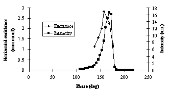
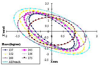
From the measured data, the transverse rms size of the proton beam has been calculated for "slices" (in phase) through the bunch. The rms beam widths have been measured for three magnetic field gradient settings in upstream quadrupoles inside tank 3. Using these data the (rms) emittance as a function of phase along the bunch has been calculated (see Fig. 5). Due to limited time for all experiments, only the measurements enabling the derivation of horizontal emittance have been made. These studies were restricted to the central part of the bunch, where the signal level ensures a good precision. However, the beam transverse behaviour can also be studied in the bunch tails using a higher dynamic gain of the signal amplifiers of the 3D-BSM. There is a significant variation of the rms beam size with phase.
The iterative use of TRACE and TRANPAR [4] allowed
the derivation of horizontal transverse emittance taking into
account space charge and acceleration in the last three gaps (between
the quadrupoles used for the experiment) for different "slices"
along the bunch (see Fig. 5 and 6). The use of the TRANPAR code
alone to reconstruct emittances showed that neglecting space charge
in this calculation process can induce an error of up to 50% on
emittances.
The horizontal rms emittance averaged over the whole
bunch and the whole pulse (0 to 75 ms)
is 2.5 mm.mrad, which is consistent with the theoretical value
from PARMILA (2.4 mm.mrad).
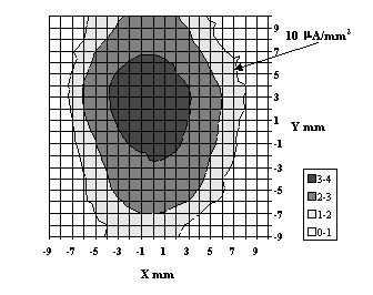
The 3D-BSM has a wide dynamic range: the signal gain
can be varied by a factor 500. It can be used for the measurement
of transverse cross-sections of the beam (see Fig. 7), including
halo because these measurements do not require rf voltage on the
deflector of the 3D_BSM [1].
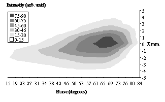
The bunch length depends on the horizontal position
(see Fig. 8a). The bunch length has a maximum for a horizontal
position different from the mean. This effect could be due to
the influence of the field created by the space charge of the
proton bunch on the trajectory of the secondary electrons ejected
from the tungsten wire[1]. However it is still unclear why this
effect is smaller for shorter bunches, when the proton density
is higher (see Fig. 8b). Therefore, it could be a real feature
of the proton beam due to a misalignement of quadrupoles in the
linac. It is possible to simulate such an asymmetry by arbitrarily
misaligning quadrupoles in tank 1 with DYNAC [5], but large alignment
errors are required. More theoretical and experimental work is
required to explain this effect. For instance, the 3D-BSM will
be studied by a computer model including the influence of the
space charge of the bunch on secondary electrons.
The study proved the effectiveness of the 3D-BSM
in monitoring both transverse and longitudinal beam parameters.
It has demonstrated that the bunch density distribution is very
sensitive to the working parameters of Linac 2. The 3D-BSM will
be an essential tool in future high intensity studies at currents
greater than 180mA at the exit of the linac.
[1] O. Dubois, S.K. Esin, A.V. Feschenko, V.A. Gaidash, H. Kugler, A.V. Liiou, A.N. Mirzojan, A.A. Menshov, A.V. Novikov, P.N. Ostroumov, L. Soby, D. Williams, "A three dimensional bunch shape monitor for the CERN proton Linac." This conference.
[2] E. Boltezar, H. Haseroth, W. Pirkl, G. Plass, T. Sherwood, U. Tallgren, P. Têtu, D. Warner, M. Weiss, "The new CERN 50 MeV Linac". Proc. 1979 Linear Accelerator Conf., 10-14 September 1979, Montauk, New York, USA, p. 66-77.
[3] D.V. Gorelov, P.N. Ostroumov, "Application of the LANA code for design of ion Linac", EPAC 96, 10-14 June, Barcelona, Spain.
[4] I.N. Birukov, A.N. Mirzojan, P.N. Ostroumov, S.A. Petronevich, "Transverse beam parameter measurements at the INR proton linac". Proc. EPAC 92 Conf., Berlin, 24-28 March, V. 2, p. 1109-1111.
[5] P. Lapostolle, E. Tanke, S. Valero, "A new method in beam dynamics computations for electrons and ions in complex accelerating elements". Particle Accelerators, 1994, V. 44., p. 214-255.