Tsumoru Shintake
KEK, Tsukuba, 305 Japan
New version of FCI(Field Charge Interaction)-code simulates beam dynamics of an electron beam running in a coupled-cavity structure, such as a multi-cell output structure in a klystron amplifier, a coupled cavity TWT amplifier, a bunching structure in an electron injector and also an rf-gun with multi-cell accelerating cavity. The particle-in-cell simulation takes into account the space charge field, the beam loading effect and energy exchange with an external circuit in a self-consistent manner.
FCI-code is 2+1/2 dimensional particle-in-cell simulation code developed by the author in 1989[1], which has been used to analyze the beam dynamics in the klystron. FCI-code has contributed to develop many high-power klystrons at KEK and in industries[2]. The FCI is a name of a code group, which includes a cavity-field calculation routine, a magnetic-field routine, a main routine of beam simulation, and post-processors. Recent version is equipped with MOVIE-PLAYER to show an animation of beam profile.
In this paper, new version of FCI is described, which simulates beam dynamics in a multi-cell coupled-cavity structure. It can be applied to several electron beam devices such as
(1) Klystron with multi-cell output cavity. (Traveling or standing wave).
(2) Electron Injector ( sub-harmonic, pre-buncher, buncher ).
(3) TWT amplifier.
(4) RF-gun( single-cell or multi-cell ).
In FCI-code, the RF-field in a coupled-cavity structure is represented by a superposition of eigenmodes in each cell ( here we call this as "cell-mode"). For example, the traveling wave in a disk-loaded structure is represented by a superposition of cell-modes, whose field intensity (cell-voltage) oscillates at the rf-frequency, but their phases are differed from cell-to-cell, resulting in a traveling wave as a group motion.
The electro-magnetic interaction between cells, which is so called "the coupling", is taken into account in a coupled-cavity circuit-model (see the next section).
The electric field of the cell-mode is represented by
![]() (1)
(1)
where ![]() is
the electric field pattern at the maximum phase. In vacuum electron beam
devices the dominant mode (TM01-mode) in a cylindrical cavity is usually
used, whose electric field is uniform around the axis. Therefore, an azimuthal
dependence was dropped in eq.(1). We define the cell-voltage by the line
integral on the "frozen electric field" along the axis as follows.
is
the electric field pattern at the maximum phase. In vacuum electron beam
devices the dominant mode (TM01-mode) in a cylindrical cavity is usually
used, whose electric field is uniform around the axis. Therefore, an azimuthal
dependence was dropped in eq.(1). We define the cell-voltage by the line
integral on the "frozen electric field" along the axis as follows.
 (2)
(2)
The subscript CF denotes "Cell-voltage on Frozen electric field". The shunt-impedance is given by
![]() (3)
(3)
This definition does not include the transit-time factor. Note that this definition is different from the accelerator definition used in theory of the high energy accelerators, which includes the transit-time factor. The relation between them is
![]() ,
(4)
,
(4)
where ![]() is the transit time
factor for a particle of speed of the light.
is the transit time
factor for a particle of speed of the light.
An electron beam running in the coupled-cavity structure interacts with cell-mode in each cell independently. The field excitation is taken into account into the equivalent circuit as an induced current given by
![]() .
(5)
.
(5)
Figure 1 shows an equivalent circuit model for a multi-cell coupled-cavity structure. The circuit equation for the n-th cell is given by

![]() ,
(6)
,
(6)
where![]() ,
,![]()
![]() ,
, ![]() : coupling constant.
: coupling constant.
![]() : detuning
of cell from the rf-frequency.
: detuning
of cell from the rf-frequency.
![]() : resonance
frequency of n-th cell.
: resonance
frequency of n-th cell.
![]() .:
cell voltage (peak) normalized by
.:
cell voltage (peak) normalized by ![]()
![]() : beam induced
current normalized by
: beam induced
current normalized by ![]()
Above normalization makes the stored energy in a simple form:
![]() .
.
Here we introduce "the quasi-steady state approximation". Since in most applications, the time variation of the cell voltage and current is much slower than the sinusoidal oscillation at the rf-frequency, we can separate the time variation into two parts: a slow change in voltage and phase and a fast sinusoidal oscillation at rf-frequency as follows.
![]() ,
,
![]()
![]() (7)
(7)
Using eq.(7) into eq.(6), we have the quasi-steady state circuit equation
.![]()
![]() (8)
(8)
In FCI-code, eq.(8) is solved by the finite difference method in time sequence.

Fig. 1. Equivalent circuit model for a coupled cavity structure.
In FCI-code, an electron beam is simulated by a flow of macro-particles
of ring shape (2D, circular symmetry). The space charge field is calculated
by solving the wave-equations of the scalar and the vector potentials by
the finite difference method. The particle motion is determined by integrating
the relativistic equation of motion in 2+1/2 dimension: ![]() ,
which takes into account the space charge field, the self-magnetic field,
the external focusing magnetic-field and the rf fields in cavities. The
details are described in references [1] and [2].
,
which takes into account the space charge field, the self-magnetic field,
the external focusing magnetic-field and the rf fields in cavities. The
details are described in references [1] and [2].
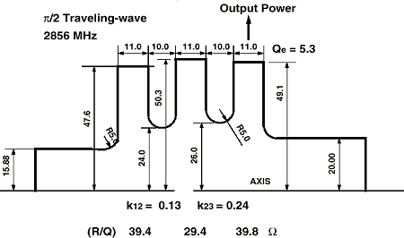
As an example, a traveling wave output structure was simulated by FCI. A structure was designed as shown in Fig. 2 and attached to the 5045-tube[4] in place of the single-cell output cavity of original design. The coupling constant and the loaded-Q were determined as follows. The steady state circuit-equation of the coupled cavity is given by[3]

![]() (9)
(9)
We use a traveling ![]() /2-mode, which requests
resonance frequencies of all cells being tuned to the rf-frequency :
/2-mode, which requests
resonance frequencies of all cells being tuned to the rf-frequency : ![]() .
Applying eq.(9) to all cells and neglecting the cavity loss (
.
Applying eq.(9) to all cells and neglecting the cavity loss (![]() ),
we have
),
we have
 (10)
(10)
To smoothly extract the kinetic energy from the beam, we assume the
same energy loss in each cell. Since we want to establish a traveling ![]() /2-mode
running with beam, the cell-to-cell distance was chosen at
/2-mode
running with beam, the cell-to-cell distance was chosen at ![]() /4
wavelength on the beam, additionally the cell-voltage must be
/4
wavelength on the beam, additionally the cell-voltage must be ![]() ,
,
![]() . Applying this
relation into eq. (10), we get the optimum condition of the coupling constant
and the loaded-Q as follows.
. Applying this
relation into eq. (10), we get the optimum condition of the coupling constant
and the loaded-Q as follows.
 (11.a)
 (11.b)
 (11.c)
We design the beam deceleration voltage close to the beam voltage of
350 kV. By taking into account the transit-time factor (~0.7), the required
total cell-voltage becomes 500 kV. Thus, ![]() .
On the other hand, the modulation rf-current on a beam is normally as high
as 1.5 times of DC-current. It is 600 A in the present case. By considering
the transit-time factor and de-bunching effect, we assume the beam induced
current as 350, 300, 250 A in the 1st, 2nd and the 3rd cell, respectively.
From eq. (11), we have the optimum coupling constants as listed in Table-1.
Once, we execute a beam simulation, we get precise values of the beam induced
currents, then we can refine the coupling constant using eq.(11), and execute
the beam-simulation again. In actual design works, we need a few cycles
of this iteration process to reach an optimum solution.
.
On the other hand, the modulation rf-current on a beam is normally as high
as 1.5 times of DC-current. It is 600 A in the present case. By considering
the transit-time factor and de-bunching effect, we assume the beam induced
current as 350, 300, 250 A in the 1st, 2nd and the 3rd cell, respectively.
From eq. (11), we have the optimum coupling constants as listed in Table-1.
Once, we execute a beam simulation, we get precise values of the beam induced
currents, then we can refine the coupling constant using eq.(11), and execute
the beam-simulation again. In actual design works, we need a few cycles
of this iteration process to reach an optimum solution.
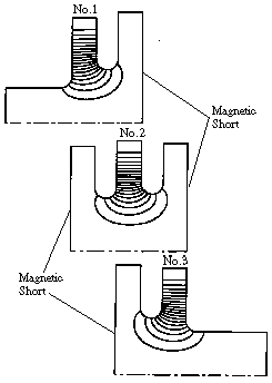
The cell-mode and shunt impedance were calculated by the DENKAI-code[5]. Figure 3 shows the electric field plots of the 1st, 2nd and the 3rd cell. In calculating each mode, the neighboring cavity was detuned by terminating the cavity wall by the "magnetic short". The cavity radius was determined to tune the resonance frequency at 2856.0 MHz.

Fig. 2. Klystron output structure using traveling ![]() /2-mode.
/2-mode.
The simulation results are summarized in Table-1. At 150 W of the input power, simulation predicted the output power of 69.2 MW, and the power efficiency of 48.5 %. The simulated voltages are about 10 % higher than the expected one. This is due to a difference between the simulated beam induced-current to the assumed one. The maximum surface electric was reduced to 13.7 MV/m, which is 51 % of the field in the original single-cell cavity design.
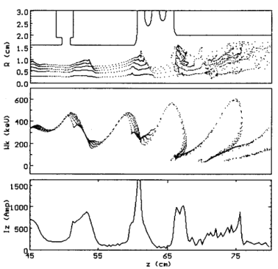
Figure 4 shows a snap shot of the beam. The top is the beam profile on (z,r) plane. Since in a traveling wave structure the aperture can be designed much wider than a single cell cavity, we can keep a large clearance for a beam to the cavity wall. Additionally, the beam deceleration is smooth and the radial kick by the cavity field is much less, resulting in a smooth profile in beam shape after the output structure. This is an important feature of the traveling-wave output-structure to eliminate collision of electrons in beam hallows on the cavity surface, and avoid accompanied rf-break-down in the output gap. The middle plot is the kinetic energy profile and bottom is the instantaneous beam current, where deceleration and de-bunching of beam in the output structure are clearly shown. The MOVIE-PLAYER shows animation of this plot on BIM-PC machine.

Fig. 3 Cell-modes in the 1st, 2nd and 3rd cell.
In this paper, the rf-field in a multi-cell couple-cavity was approximated by the superposition of cell-modes, and whose voltages were calculated by the equivalent circuit model. In case of a small coupling, the energy transfer per one cycle along cell-to-cell is much smaller than the stored energy in one cell, therefore this approximation works very well. However, in a case of a large coupling, such as in a klystron output structure, we has to pay attention on errors in the approximation. In order to verify accuracy of the simulation, we are continuing studies, such as comparison of cell-mode model to standing wave modes in coupled cavity without beam, or direct finite-difference modeling of coupled-cavity structure with beam. The code is also under testing on several existing cases, such as X-band klystron having multi-cell output cavity, and an electron injector with traveling-wave buncher.

Fig. 4. Snap shot of simulated beam.
Table 1
Cavity parameter |
|||
| f0 | (R/Q)CF | QL | |
| No.1 | 2856.0 | 39.4 | 2000 |
| No.2 | 2856.0 | 29.4 | 2000 |
| No.3 | 2856.0 | 39.8 | 5.3 |
| k12 | 0.13 | ||
| k23 | 0.24 | ||
| Beam Parameter | |||
| Beam Voltage | 350 | kV | |
| Beam Current | 408 | A | |
| Drive Power | 150 | W | |
| Simulation Results | |||
| Vc (kV) | Ic (A) | ||
| No.1 | 177.6 | 345.2 | |
| No.2 | 187.2 | 279.3 | |
| No.3 | 170.9 | 167.8 | |
| Surface Electric Field | 13.7 MV/m | ||
| Output Power | 69.2 MW | ||
| Power Efficiency | 48.5 % | ||
[1] T. Shintake, "FCI field charge interaction program for high power klystron simulators", Proc. 1989 Particle Accelerator Conf., Accelerator Science and Technology, March 20-23, 1989, Chicago, USA
[2] T. Shintake, "Klystron simulation and design using the Field Charge Interaction (FCI) code", Nucl. Instrum. and Method in Physics Research A363 (1995) 83-89
[3] E. A. Knapp, B. C. Knapp and J. M. Potter, "Standing Wave High Energy Linear Accelerators", Review of Scientific Instruments, Vol. 39, No. 7, 1968, pp. 979-991
[4] T.G.Lee, et.al., "A Fifty Megawatt Klystron for the Stanford Linear Collider", SLAC-PUB-3214, Sep. 1983(A)
[5] T. Shintake, "User's guide to DENKAI", KEK Report 91-3, June 1991 A/D