A simple device for generating
powerful RF oscillations in the frequency range of 100-250 MHz
is considered. The two-gaps cavity is based on the quarter-wavelength
coaxial line loaded by drift tubes. Frequency tuning is accomplished
by using the movable shorting plunger. A permanent electron beam
being modulated at the first gap return the energy at the second
one. The additional tube with the permanent decelerating potential,
introduced into the main drift tube, allows to decrease the drift
tube length and keep the excitation conditions in frequency tuning.
Both autogeneration and amplification modes are under consideration.
RF-parameters of the cavity and experimental results are described.
At present there is a number of scientific and applied problems, for the decision of which it is necessary to have RF generator with power up to hundreds kW with smooth adjustment of frequency in a wide range. At the same time, made and used the powerful lamp generating devices are allowed rebuilding up to by several percents. As far as the frequency change in wider range requires agreed rebuilding of several resonant contours of amplification cascades. Conventional klystron and magnetron devices not allowed significant rebuilding owing to specific character of a volumetric resonators design. Generating devices on TWT base can not supply required exit power value.
To ensure a condition of beam resonance interaction with RF structure in a wide range of wave length it is possible by changing system period or electron speed. However, it is practically impossible to change RF structure space charge by virtue of the constructive reasons. On the other hand, it is required a relative electron beam with energy 100 keV for high-power reception. The speed of one makes size 0,5c. The speed reduction, for example, in two times would result in this case in injection beam essential loss. Other the discussed scheme defect is a large RF system period length: at the electron energy 100 keV and wave length 2 m the period will make 1 m. That will cause to excessive general accelerator length growth and efficiency fall. Besides the injection energy change can ensure synchronism maintenance at frequency rebuilding only on an initial structure site.
That to minimize installation dimensions and to ensure electron beam resonant interaction with a resonator in wide range of wave length scheme with electrical adjustment of a structure effective length is offered. This scheme is based on system with drift tubes. Inside ones are coaxial located additional isolated tubes, those are under electrons slowing down (or accelerating) constant potential. Thus the electrons speed inside tubes can vary depending on value and sign of potential. It enables to support synchronism at frequency rebuilding and constant injection energy.
As the first section of a generating device based on these principles is developed double-gap buncher resonator with drift tubes. One capable to work as in a mode of self-excitation (that is independent generation) and as a buncher with independent excitation. In the self-excitation mode the electron beam receives modulation on energy in a first backlash, is grouped in drift tube and gives back energy (brake) in the second backlash. Distance between backlashes centers is 200 mm. Thus on frequency 150 MHz electrons with relative speed =0,5 past first backlash in optimum group phase (1=-/2 in cosine readout) and fall in the second backlash in a phase 2=-/2+, that is close to the slowing down half-wave top. With frequency increasing the significance 2 is increased and for preservation of self-excitation optimum conditions it is necessary to submit breaking potential on internal tube or to reduce injection energy. Self-excitation conditions on high frequencies are possible also at multiple flight corners. For example, 5/ 4.
The developed resonator design
is schematic submitted on fig. 1. Resonator contain vacuum jacet
1
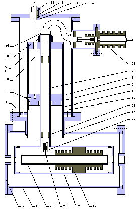
with face flange 2 and vacuum volume 3. In ones places own rebuilding resonator. It consists of a cylindrical screen 4 with face cover 5 and internal coaxial guide 6. On guide is fixed drift tube 7. In a resonator is present a mobile shorting piston 8 with sliding silvering contacts 9. The piston can be moved through coaxial at the help of the rod 10. For restriction of moving and azimuth turn prevent is stipulated restrictive pin 11, which moved in cylindrical RF screen longitudinal split. The design provides a piston moving without vacuum infringement through a traffic input device. Bush 12 is placed in a framework 13 and upsets by a rubber lining 14, the effort on which is created at the help of a device 15. The smooth surface of the rod permits to move the piston and save vacuum in systems at a level 10-5-10-6 Torr. The cylindrical screen 4 RF contact with jacet 1 is provided by special copper ring compression 16, which is established in stipulated slot and key between a jacet and screen at screw 17 protracting. Thus, drift tube should be fixed in the resonator by the tightening ring 18 only after screws 17 protracting.
In drift tube 7 on isolator 19 coaxial fixed potential tube 20, on which constant voltage feeds. The copper guide is used for transmit voltage. High-voltage copper guide 21 placed in rigid ceramic tube. Ones, in turn, place in isolation tube. Isolation tube is fixed in internal coaxial at the help of bushes 23 and exit bushes 24. Further high-voltage guide is removed from vacuum chamber through isolator 25.
The made installation is represented reasonably simple and at the same time reliable for study powerful RF oscillations in a wide wave lengths range.
Maximum rebuilding range of resonator own frequency makes 117-235 MHz and is limited from below by coaxial line length. The top limit is connected to a significant drift tube length, which at close to it a shorting piston situation represents large part of a quarter wave line. Own resonator quality is weak drops with frequency decrease from 1300 up to 800. It is connected with two circumstances:
1. It is necessary to reduce magnetic field screening of pulsing focusing tube. So coil drift is executed from stainless steel and have become in comparison with copper coaxial much more resistance. At a piston approach to tube relatively more part of currents flow on tube, that results in quality decrease.
2. At high frequency the resistance of mobile contacts grows.
Separate problem is choice of connection factor with a making path value. By use of a resonator as a buncher with independent excitation optimum is the critical connection. If the resonator works in a selfexcitation mode, the choice is not obvious. On the one hand, at small connection conditions of selfexcitation are facilitated at small beam currents. From the other hand, connection should increase for effective generated power transfer to a load. Hence, for ground choice of a connection factor value in a selfexcitation mode and system power efficiency optimization it is necessary to carry out detailed numerical accounts and subsequent experimental research.
Other problem of a broadband generator is its coordination with a path in all frequencies range. In considered construction individual connection unit in a kind of a loop is used. Loop is located near to internal coaxial line guide in the field of junction with drift tube. On first stage the resonator was investigated in a independent excitation mode on frequency 148,72 MHz. Thus close to critical (1,2) connection value was supplied. The rebuilding in the low frequencies area results in connection reduction. In the area of higher frequencies connection, opposite, grows. It is stipulated as by shorting piston reactive impedance change, as its situation relatively shorting piston. Here in after, for preservation of coordination conditions, probably, expediently to use capacitor connection, as far as in this case the effect of reactivity change at frequency rebuilding can be compensated (completely or partially) by connection unit situation displacement relatively shorting.
The RF generator model research
was conducted on a experimental stand, the block diagram of which
is submitted on fig. 2. Stand contains following main elements:
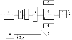
electron injector 1, electromagnetic lens 2, compressor coils 3, focusing solenoid 4, double-gaps buncher 5, electrons collector 6, external RF path 7 and load 8. The lens 2 and coils 3 formed a site cross compression of a electron beam in adiabatic increasing longitudinal magnetic field. The field value changes from significance 0,005 Ò on injector cathode up to 0,2 Ò on compressor output. The beam diameter decreases from 30 mm up to 8 mm. The compression site length is equal 1 m.. The resonator placed inside the solenoid 4. One creates on the installation axis close to a similar magnetic field by size up to 0,25 Ò. The lens 2 feed scheme is operated in a continuous mode, but the coils 3 and solenoid 4 - in pulsing.
The described system of the electron beam formation permits to receive pulsing electrons beams with energy up to 100 keV and current up to 20 A at a pulses duration 100 s.
As far as for maintenance of the best electrons beam grouping it is desirable to have more electrons slowing down in potential tube, its potential should be approximate to injection potential up to value, determined by optimum current flow conditions. For experiments at a initial stage a settlement ratio of high-resistance divider shoulders resistance equals 0,85 was chosen. At high-voltage system tests on a idle running (without electron beam) the measured relation of potentials on tube Ut and injector Ui has appeared close to this significance. At the same time, at experiments with beam for the account of current load and hit electrons part on tube redistribution of potentials occurred. Therefore the significance Ut/Ui was increased and actually has appeared close to 0,95. The generation was observed at injection voltage exceeding by 12 kW.
Experimental electron current
oscillograms on collector is shown on fig.3. The form of the flat
top of a electrons current pulse is close to sine with period
10 ns.
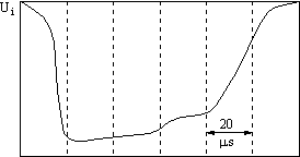
The resonator excitation process is largely defined by the electrons beam geometrical characteristics, as far as the generation takes place only in a in comparison narrow range of electron injector magnetic field B value change. That is exists optimum significance  in relation to electrons energy. We shall note, that at the increase Ui the optimum significance B also grows.
The RF oscillations occurrence in a resonator is accompanied by signal arising on detector in external RF path and eroding of the electron current pulse flat top on the collector (a dotted line on fig. 3, a continuous line shows the pulse form at generation absence). Availability of electron beam RF modulation in the sine form signal is well visible on oscillogram (fig.3). The modulation period within the limits of measurements error well coincides significance 0,67 ns, appropriate resonator working frequency equal to 148,72 MHz (the modulation frequency coincides resonator self-excitation frequency).
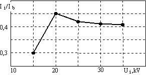
Dependences of constant Ib
and of the first harmonic amplitude variable I1 of
a making electrons current signal on a collector from the value
Ui are shown on fig.4.
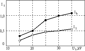
Both signal are increased with the growth Ui. The relation I1/Ib dependence from the significance Ui is submitted on fig.5. In accordance with the increase Ui the share of the first harmonic grows, reaches a maximum, and then decreases up to some significance, about constantly.
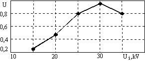
RF amplitude signal U dependence
in external RF path from Ui is shown on fig.6. Availability
of optimum significance Ui at which maximum U is reached
is visible. It is connected as appear with selfexcitation optimum
phase conditions (groped electron beam falls in the second backlash
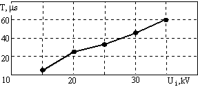
in close to a break phase). At the same time the pulse duration
T RF signal continuously grows at the increase Ui (fig.7).
At a following stage resonator serviceability check was conducted at other significance of its own resonance frequency. For this purpose by shorting piston 8 moving (fig.1) the working frequency was biased in the lower frequencies area (piston was moved closer to input voltage unit on 800 mm). The experiments results have appeared similar above described. The resonator selfexcitation frequency was measured with the help of a spectrum analyzer and has appeared equal 132 MHz.
Thus, is experimentally proven, that creation of waves lengths meter range generator with smooth frequency rebuilding in a wide range (in some times) is possible at enough large efficiency. For the entered power level increase and the maximum efficiency mode realization expediently work making on manufacturing and start of the RF structure second series. One can be based on the same principle of action, as described above.