The RF power upgrade systems with microwave energy
compression are using for accelerating wave power increase [1-3].
The energy compression systems (ECS) with a resonant loading present
the certain interest for practical use because of their specific
properties [4]. They are capable to increase an accelerating wave
power up to 50...100 times (up to 20 dB) and keeps this wave in
accelerating structure for a longer time then conventional ECS.
The resonant load is an essential part of the system and renders
influence significantly on its parameters. The system consists
of two connected resonators, one of which is using as a storing
element and the second - as a load. Load may be a standing or
a traveling wave resonator (TWR) formed by accelerating structure.
Beam loading effects would change the properties of RF field in
the load resonator. ECS characteristics and the accelerated beam
parameters are discussed.
The main principle of the system with resonant loading operation is based on using connected resonators [4]. Wave emitted from storing cavities (SC) pass through TWR (see Fig. 1) and becomes incident wave for SC. The resultant wave amplitude at the accelerator structure is equal sum amplitudes of those waves. This process continues while all energy primarily stored in SC passes by terns to TWR. So it causes significant field increase at accelerating structure.
Schematic drawing of the ECS with resonant load is
submitted on Fig.1. Accelerating structure input and output

connect through switched coupler and SC and form the TWR. The switched coupler transfers the system operation mode from storing energy to its use. During the energy storing period (state A) the coupler connects generator output to storing cavities and the acceleration structure output - to an absorbing load. To use the stored energy (state B) the coupler is switched in such way that the acceleration structure output becomes connected to storing cavities, forming TWR.
At state A (see Fig. 2) energy storage occurs in
SC. The wave, reflected from storing resonators, passes through
a TWR and arrives in a load. When the energy storing process ends
the coupler transformed in state B. The wave coming to SC is a
wave leaving from accelerating structure. A wave phase shift in
a TWR is chosen so that the wave coming on SC has the same phase
as the wave emitted from it. Amplitude of a wave circulating in
TWR ring will grow so long as all accumulated in SC energy will
not pass completely in TWR. After this the return swapping of
energy from TWR to SC will begin. The qualitative graph of the
circulating in TWR wave average amplitude variations is shown
on Fig. 2.

Traveling wave resonator is forming at the end of storage period (at moment t0) by the switched coupler. RF generator is connected with an absorbing load and accelerating section output - with storing cavities. The wave, emitted from the SR, is added to a wave circling in the TWR. In this case the amplitude of a summarized wave at the acceleration structure entrance during the energy use period is described by a following expression [4]:

where:

;
N = [(t-t0)/T] - number of wave revolutions in TWR, T - time duration of one turn-over of a wave in a TWR.
For function F(-n, 1, A) evaluation one can use formula:
where F( 0, 1, A)
= 1 and F (-1, 1, A) = 1-A.
The expression (1) describes microwave amplitude at accelerating section without current loading. Coupling factor depends on the storing energy duration period t0.
In case, when the current loading appears essential, it is necessary to take into account changes of wave amplitude falling on cavities. Using principle of independence of fields, it is possible to consider that two waves exist: one wave is connected with RF energy in SC, second - will be formed by electron beam. The expression for field amplitude of the beam radiation wave at any point of accelerating section with coordinate z, has a kind:

Where designations are used:

, I - beam current,
R - shunt impedance of accelerating section, - group velocity
of accelerated wave, t1 - beam injection moment,
l - accelerator structure length.
The resulting amplitude of a high-frequency wave at accelerating section input is determined by addition of two waves Ew (t) and Eb (t):
(3)
Analytical expression of beam energy is enough difficult problem. For this reason the determination of beam energy of linear accelerator was carried out in numerical kind by using formula:
(4)
ESC with resonant loading give increased amplitude
RF wave on extent several turn-overs of a wave on TWR. So it can
receive much longer pulses of an accelerated beam in comparison
with other type compression systems. For example, we have obtained
RF pulses with 15...17 dB multiplication factor and about 0.5
s pulse duration for accelerating section filling time about 24...40
ns [4]. The electric field is considerably changed in time at
accelerating section at one turn-over period. However, it does
not result in increase of beam energy spectrum. It is possible
to assume, that stored in traveling wave resonator energy is almost
in accelerating section. So the beam energy is close to constant
during one turn-over period.
Calculation was made for following parameters of ESC and accelerating section: power of the generator output P0 = 10 MW, Q-factor Q0= 90103, shunt impedance of accelerating section R = 40 MOm/m, t0 = 2.5 s, power decrease per unit of acceleration section = 0.04 and 0.08 m-1 , accelerator section feeling time T = 40 and 60 ns.
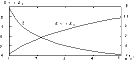
To achieve maximum beam energy it is need choice
coupling factor for an energy storage period t0.
Dependencies of maximum value Ew/E0 and
optimum coupling factor are shown on Fig. 3.

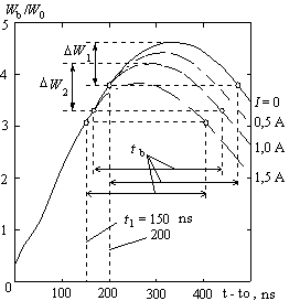
The accelerator beam energy Wb
(normalized to W0 - accelerator energy without
any ECS) depend upon time t as shown at Fig. 4. Width electron
energy spectrum remains practically constant (W1W2)
for current values from 0 up to 1.5...2 A. At given current pulse
of beam duration tb the influence of a beam
loading has an effect on average energy of particles. The maximum
beam energy with minimum spectrum width can be achieved by appropriate
choice of an injection moment t1. Spectrum width
less then 3...5% can be obtained for current pulse about tb
2.3T for pulse current values up to 2 A.

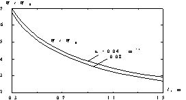
The typical beam energy dependence from accelerating
structure length l at output TWR accelerating section is
shown in Fig. 5.

The normalized energy W/W0
of accelerated beam grows with reduction of length accelerating
section (filling time of accelerating section is proportional
to its length). Absolute value of beam energy appears higher for
longer sections. Therefore to achieve higher energy long accelerating
of section should be apply.
[1] Farkas Z.D., Hogg H.A., Loew G.A., Wilson P.B. SLED: A Method of Doubling SLAC's Energy, - Proc. of the 9th Int. Conf. on High Energy Accelerators, 1974, SLAC, pp.576-583.
[2] Bogdanovich B.Yu., Ignatyev A.P., Senyukov V.A. RF Pulses with Flat Output Generation in RF Power Upgrade Systems. - Particle Accelerators Conf. San Francisco, California, 6-9 May 1991.
[3] Shalnov A., Bogdanovich B., Senyukov V. RF-Energy Compression Systems for Electron Linacs. - Particle Accelerators Conf. (PAC'95) Dallas, USA, May 1-5, 1995. Bulletin of the American Physical Society, May 1995, Vol.40, 3, p.1106.
[4] Shalnov A., Bogdanovich B., Ignatyev A., Senyukov V. RF-Energy Compression System with Resonant Loading. - Particle Accelerators Conf. (PAC'95) Dallas, USA, May 1-5, 1995. Bulletin of the American Physical Society, May 1995, Vol.40, 3, p.1106.