The electron gun for the Daresbury SRS linac injector has been modified to use the cathode-grid assembly from the Eimac planar triode 8755. The gun now has improved beam characteristics, is more reliable and the cathode assembly is quicker and easier to change. This paper describes the assembly of the electron gun, and then the re-conditioning of the cathode highlighting the vacuum environment. The action of the grid modulation system on the electron beam, which pre-bunches the electron beam, is described, and typical gun characteristics are shown.
Proposed developments to the gun system are discussed.
Daresbury Laboratory operates the UK's national synchrotron light source, the SRS. It is operational for approximately 7000 hours a year, providing synchrotron radiation used by many varied scientific disciplines. The electron storage ring energy is 2 GeV and the beam lifetime is in excess of 30 hours at 200 mA. The storage ring is filled to 250 mA once every 24 hours.
The injection system consists of a 80 kV electron gun feeding a 10 MeV S-band electron linac, the electron beam is accelerated to 600 MeV in a 500 MHz booster synchrotron. The beam is injected into the storage ring at 600 MeV and the energy ramped to 2 GeV. The injection process takes approximately 20 minutes. Consequently the gun injection equipment is operational for less than 1 hour per day.
The electron gun has been modified to use the cathode-grid
assembly from the Eimac planar triode 8755 [1]. This gives improved
beam characteristics over the previous system, it is more reliable
and the cathode assembly is quicker and easier to change. The
paper describes the assembly of the electron gun, and the re-conditioning
of the cathode, highlighting the vacuum environment. The action
of the grid modulation system, which pre-bunches the electron
beam, is described, and typical gun characteristics are shown.
Proposed developments to the gun system are also discussed.
The original electron gun was similar to the design by Willard [2] for the Manchester Christie Hospital Linac. It contained a 1 inch (25.4 mm) spherical oxide cathode with a separate de-mountable grid, which was modulated at 500 MHz. When the cathode failed the cathode - grid assembly was de-mounted, and the cathode sprayed with the usual carbonate mix (barium, calcium and strontium). The carbonates were converted to oxides, and when this was completed activation of the cathode took place. This process took several hours, and satisfactory conversion and activation could never be guaranteed. As this process took place while the gun was attached to the linac, the decomposition products of the carbonates could have harmful effects on the vacuum surfaces of the linac.
The gun has now been modified. Figure 1 shows the
mechanical arrangement of the present gun. A miniature ceramic
- metal planar triode, Eimac type 8755, has been modified to be
used as the cathode grid assembly of the gun. The triode can be
used up to frequencies of 3 GHz. The cathode is a conventional
oxide coated cathode, but the heater power is only 10 watts, a
factor of ten lower than the original.
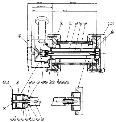
The triode is inserted in the gun assembly which
is connected to a temporary heater supply, with the heater voltage
set to about 2 V to keep the activated cathode temperature above
150 oC. The triode anode and body ceramic are broken
off, and the beam forming electrode attached. The gun assembly
is bolted to the linac and the gun evacuated, whilst maintaining
the cathode temperature. Haas and Jensen [3] found that by keeping
the temperature to 150 oC cathodes are not poisoned
when exposed to air as the oxides are converted to hydroxides
and the hydrate is prevented. The emission capabilities are preserved.
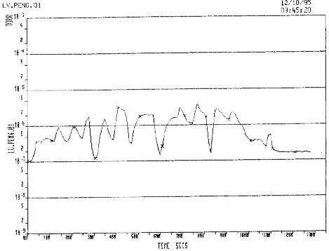
When the vacuum pressure is better than 10-7
torr, the heater voltage is gradually increased, keeping the vacuum
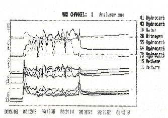
pressure below 10-5 torr. Figure 2 shows the typical
vacuum pressure variation during this re-activation process, and
Figure 3 the residual gas analysis at the same time. Note that
the water peak increases initially, but that it is the methane
peak that determines the overall pressure.
The installation and re-activation process is simple
and quick, taking only 4 or so hours. The cathode life is typically
two years, but recently improved vacuum conditions have extended
that time.
Figure 4 shows the electrical layout of the gun system. The gun has to produce a 400 nS 80 keV bunch of electrons 10 times a second. The action of the triode is used to pre-bunch the beam before injection into the linac.
A three quarter wavelength coaxial cavity is connected
to the gun, and sits at the gun HT, which is provided by a half
sine wave pulse modulator, giving a -80 kV pulse. The heater power
supply is at HT potential. There is a 0 to -200 V grid bias supply,
and the 500 MHz grid modulation is fed via an 80 kV waveguide
isolator.
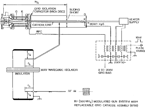
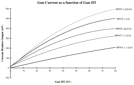
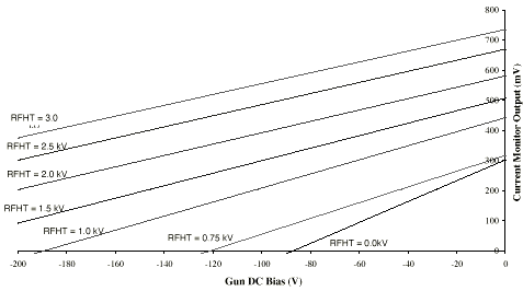
A current transformer type monitor with a bandwidth
of 500 MHz, but followed by a 10 MHz filter monitors the gun current,
Io. Typical gun characteristics are shown in figures 5a, the gun
current as a function of gun HT for various values of grid RF
modulation -dc grid bias set to -100 V, and 5b, gun current at
a fixed HT at -80 kV as a function of DC grid bias for various
values of grid RF modulation. These characteristics should be
compared with the triode characteristics in the Eimac data sheet
[1]. The differences in the slopes in figure 5b is because the
output voltage of the Io monitor is proportional to average current,
and the conduction angle is smaller the greater the RF amplitude.
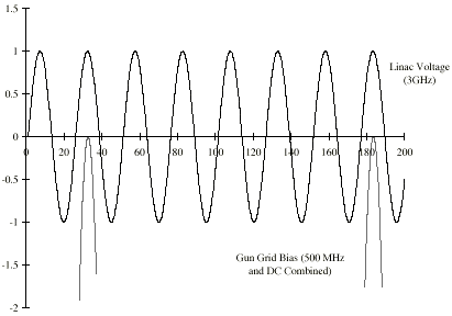
The SRS linac does not have a pre-buncher cavity,
but pre-bunching is achieved by the DC and RF biasing of the gun
grid. The linac accelerating voltage is a 4 mS, 4 MW pulse at
3 GHz. The voltage is phased locked to the 500 MHz gun grid modulation.
As can be seen from figure 6, by accurate phasing of either of
the grid modulation or the accelerating voltage and a large grid
DC offset short current micro-pulses can be injected into the
linac. The more negative the DC bias the shorter the current pulse.
For a small but significant period, the SRS operates in single bunch mode, where only one of the 160 RF buckets in the storage ring is filled with electrons. At present this is achieved with a chopper system operating on the 10 MeV beam in the flight path between the linac and the booster synchrotron. Recently investigation has started on using the gun grid modulation system to produce the single bunch and other bunch patterns [4].
The grid modulation equipment will sit at the HT
potential, whilst triggering and clock pulses will be fed via
optical fibre.
The electron gun for the SRS linac injector uses
the already activated cathode-grid assembly of an Eimac 8755 planar
triode. The installation is simple and quick, and the cathode
life is relatively long. The measured gun
characteristics are as expected and follow the original triode
characteristics. The action of the RF and
DC biasing of the gun grid perform some pre-bunching for the linac.
In the future the grid modulation system will provide
single bunches and any required bunch pattern.
I would like to thank Mr. Brian Taylor for the original
idea of using a planar triode as the grid-cathode assembly for
the SRS linac electron gun.
[1] Eimac Technical Data 8755, Varian EIMAC Division, 301 Industrial Way, San Carlos, California 94070.
[2] J.Willard, A High Currnt Electron Gun Suitable for use Down to 1 nanosecond Pulse Length. IEEE Trans. Nuc. Sci. June 1967.
[3] G.A.Haas and J.T.Jensen, Preconversion of Oxide Cathodes, Rev. Sci. Instr., 30, pp 562 565, July 1959.
[4] C.W.Horrabin and D.M.Dykes, DIAMOND Low Power
RF System, Proceedings of the 5th European Particle
Accelerator Conference (EPAC - 96), Sitges, 1996.