All-Electrostatic Split LEBT Test Results*
John W. Staples, Matthew D. Hoff and Chun Fai Chan
Lawrence Berkeley National Laboratory
Berkeley, California 94720, USA
Abstract
An all-electrostatic LEBT for an RFQ has been assembled and tested with
beam. The LEBT includes two quasi-einzel lenses, allowing a wider range
of Twiss parameters to be accommodated, and the lenses are split into quadrants,
allowing electrical steering of the beam. Moreover, mechanical steering
by moving the entire LEBT with a special low friction vacuum joint was
also demonstrated. The LEBT was tested with unanalyzed protons from an
RF-driven bucket source by measuring the beam directly and by measuring
the transmission through a subsequent RFQ as a function of LEBT electrode
parameters. Agreement between calculated LEBT beam characteristics and
actual measured values is excellent. This LEBT offers fully unneutralized
beam transport with steering and two knob control of exit Twiss parameters,
and can be applied to negative hydrogen as well as proton beams.
Introduction
An advanced, all-electrostatic LEBT has been built and successfully tested. This new design [l] offers several advantages over previous LEBT designs, particularly for injection into RFQ accelerators.
The strongly convergent beam required at the RFQ entrance, along with precise beam steering requirements has proven to be a formidable task as focusing and steering errors can easily reduce the performance of the RFQ. The usual method of magnetic solenoid or quadrupole transport results in space charge neutralized transport, which may be unstable in the presence of any intensity modulation noise from the ion source, and the lack of sufficient steering or matching capability often results in betatron function mismatch at the RFQ entrance.
The all-electrostatic LEBT designed and built by the Ion Beam Technology
(IBT) group at LBNL eliminates the neutralization problem and offers several
other advantages. This new design incorporates two electrostatic lenses
that allow a wide range of matching conditions (Twiss parameters) to be
established, insuring betatron function match to an RFQ accelerator. The
design has exceptionally low aberrations, offers beam steering, in both
angle and displacement, and is physically compact.

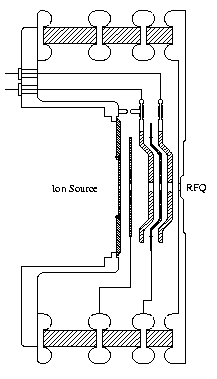
Figure 1, Electrode Arrangement
Figure 1 shows the layout of the LEBT inside the re-entrant support insulator. The ion source resides in the cylindrical cavity on the left. The total acceleration potential is 40 keV with 59 kV across the first (extraction) gap. The two thick electrodes comprise the variable-voltage einzel lenses.
Beam steering is incorporated by splitting both einzel lenses into four quadrants and applying a balanced deflection voltage across opposing quadrant pairs. Up to ˜ 7 mrad deflection is attainable from each of the two lens electrodes with 1 kV across opposing quadrants. In addition, the entire source and LEBT assembly can be moved transversely during operation in both planes by up to ˜ 4 mm with 40 micron reproducibility. This combination of electronic and mechanical steering guarantees optimum steering of the beam into the RFQ.
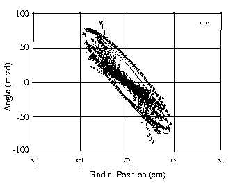
Figure 2 shows the beam envelope from the ion source to the RFQ match
point and Figure 3 the r-r phase space predicted by the WOLF ion source
code (ref in [l]). The smallest lens aperture radius is 0.5 cm at the final
electrodes on the right, the last one representing the beginning of the
RFQ vane and the immediately preceding one the exit aperture of the LEBT
itself.

Figure 2, Beam Envelope through LEBT

Figure 3, WOLF-Predicted r-r Phase Space
Test Procedure
The LEBT performance was first measured with an Allison-type emittance
scanner[2] substituted for the RFQ with the first analyzer slit located
20 cm downstream of the RFQ match point. The pulsed 30 mA beam current
was measured with a toroidal current transformer at the exit of the LEBT.
The nominal voltages for the electrodes, referred to ground, are listed
in Table 1.
| Ion Source Body | 40 kV |
| Extraction Electrode | -16 kV |
| First Focus Electrode | 35 kV (nominal) |
| Intermediate Electrode | 16 kV |
| Second Focus Electrode | 36 kV (nominal) |
| Ground End | 0 kV |
Table 1. Electrode Voltages
The first and second focus electrodes were varied over a matrix of 33
to 37 and 33 to 38 kV, respectively, in 1 kV steps, and the Twiss parameters
a, b and E were measured. These were compared to the values predicted by
the WOLF calculation for several representative values of the focus electrode
voltages, the data showing good agreement between the predictions and the
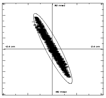
measurements. Figure 4 shows a typical emittance plot, with the ellipse
representing the shape of the RFQ acceptance (but at a smaller emittance
to emphasize the congruence of the ellipses).

Figure 4. Measured LEBT Beam Emittance
At a total current of 30 mA, measured with the toroidal current transformer,
the following emittances and Twiss parameters were measured. In this case,
the electrode voltages were set to the nominal values indicated above and
the measured emittance back-projected a distance dback, assuming
ballistic transport, to a point 20 cm upstream of the plane of measurement,
corresponding to the original WOLF calculation and
to the match point of the RFQ. Table 2 lists measurements done on separate
days, showing the excellent consistency of the measured values, and the
results of the WOLF calculation. Also listed are measured values back projected
19.5 cm, which give better agreement to the WOLF calculation, indicating
a mere 0.5 cm discrepancy of the longitudinal position of the RFQ match
point between the measured and calculated values for nominal focusing electrode
potentials.
|
Run Date |
d back (cm) |
b (cm) |
a |
E rms,U (cm-mrad/p) |
E rms,U (cm-mrad/p) |
|
27 Sept 95 |
19.5 |
7.8 |
1.95 |
1.483 |
0.137 |
|
|
20.0 |
9.9 |
2.26 |
1.483 |
0.137 |
|
28 Sept 95 |
19.5 |
8.9 |
2.11 |
1.454 |
0.134 |
|
|
20.0 |
11.2 |
2.41 |
1.454 |
0.134 |
|
2 Oct 95 |
19.5 |
8.9 |
2.22 |
1.260 |
0.116 |
|
|
20.0 |
11.3 |
2.55 |
1.260 |
0.116 |
|
WOLF |
|
7.45 |
2.87 |
1.110 |
0.105 |
Table 2. Measured and Calculated (WOLF) Twiss Parameters
Electrical steering
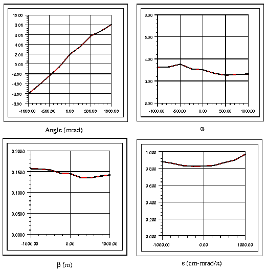
Angular beam steering is accomplished at the two focusing electrodes, split into quadrants, by applying a balanced transverse field at those points. Each pair of opposing quadrants of each of the two focusing electrodes can be operated at a voltage offset from the mean by as much as ˜ 500 volts, or 1000 volts across an opposing pair. The angular deviation of the beam was determined by the emittance scanner, along with any variation in the Twiss parameters, including the beam emittance.
Figure 5 shows the variation in exiting beam angle, and the variation
of the Twiss parameters and emittance when the voltage across an opposing
pair of quadrant segments in the second focusing electrode is varied from
-1000 to +1000 volts. The angular deviation is quite linear with voltage
and the Twiss parameters and beam emittance are only slightly affected
at large steering angles.

Figure 5. Steering, Twiss parameters vs. Quadrant voltage unbalance
Coupling to an RFQ
In the second phase of the experiment, the LEBT was coupled to an 800 keV, 400 MHz RFQ [3] manufactured six years ago at LBNL designed with an injection energy of 40 keV and 50 mA beam current. The LEBT was designed to match the Twiss parameters of the RFQ with a generous margin of adjustability by varying the potentials of the two focus electrodes.
The transmission of the RFQ was calculated, using PARMTEQ for a range of input Twiss parameters. The effect of steering, both angular and position on the RFQ transmission was measured, verifying the initial alignment of the system The optimum transmission occurred with minimum electrical steering and with the initial mechanical alignment position.
The focusing electrode voltages were varied over the same matrix of values for which data were taken with the emittance scanner. The transmission of the RFQ over the range of Twiss parameters available from the LEBT matched very well with the predicted transmission calculated by PARMTEQ for a mismatched input beam. The maximum transmission was experimentally found at almost the exact focusing electrode voltages predicted by WOLF. We can thereby conclude that the actual acceptance of the RFQ is in agreement with the PARMTEQ prediction, and that the measured beam parameters from the LEBT show excellent agreement with the WOLF calculations over a wide range of focusing lens parameters.
Further measurement taken after the RFQ was removed from the beam line
showed the species distribution from the LEBT was approximately 64% H+,
17% H2+ and 19% H3+. The RFQ
accelerates only the H+ component, and the expected transmission
of the RFQ was expected to be only 59% for the H+ species, due
to a poor choice of geometry of the vane tips. (A r^
= 0.75r0 constant transverse radius geometry was used.
Subsequent simulations with the 8-term PARMTEQ-H [4] showed that this geometry
was a poor choice and a r^ = 1.0r0 geometry would
have given much better transmission.) The total current (all species) injected
into the RFQ was about 18 mA, which should result in 6.8 mA of accelerated
H+ beam. About 5.5 mA was accelerated, 81% of the expected value.
This small discrepancy has not been resolved to date.
Chopping Experiment
Recently, LBNL has joined a team to develop the front end of a proposed pulsed spallation neutron source, which incorporates a 1GeV linac and a storage ring [5]. The beam circulating in the ring requires a 35% circumference gap with a dark current of 10-5 of the rest of the circulating bunch. To establish this very deep gap, choppers will be placed at the ion source, in the LEBT, and a fast, 2.5 nsec chopper at the 2.5 MeV point in the linac. An experiment was prepared for this LEBT to test the feasibility of fast (1 MHz) chopping at the 40 keV level.
In the first phase of the experiment, a high-voltage pulser provided
a ˜ 1500 volt pulse, rising in 100 nsec and decaying some-what more slowly,
to opposite quadrants of the second focusing electrode to deflect the beam
into a 0.6 cm diameter aperture located at the LEBT exit. With 2.7 kV across
the opposite quadrants the beam was fully extinguished with a risetime
comparable to the risetime of the pulse generator. Transit time in the
LEBT itself limits the rise/fall time of the chop to about 15 nsec, and
the 2.5 nsec risetime travelling wave chopper at the 2.5 MeV level will
sharpen up the edge of the chop. The slower LEBT and ion source choppers
contribute the very low dark current in the middle of the chop, and reduce
the heating of the 2.5 nsec chopper beam stop.
Future Plans
The operation of this LEBT has been so successful that a minor variant
of it will be used in the low-energy part of the injector for a proposed
National Spallation Neutron Source [5]. Added to the basic LEBT design
shown here will be the beam chopper, a segmented thin Faraday cup that
pivots in from the side and a pivot-in one-way vacuum gate valve, both
located between the last focusing electrode and the ground end, operated
with the last focusing electrode at ground potential.
Acknowledgments
The authors thank all those who worked tirelessly on this project, including
Rick Gough, Ka-Ngo Leung and his ion source group, Jim Ayers and his electronics
technicians, and Bob Aita and his mechanical technicians.
References
[1] Chun Fai Chan and John Staples, A Compact Double Einzel Lens LEBT with Steering for H+ Beams, Proceedings of the 1994 Linear Accelerator Conference, Tsukuba, p. 594.
[y Paul W. Allison et al, An Emittance Scanner for Intense Low-Energy Ion Beams, 1983 Particle Accelerator Conference, Santa Fe, p. 2204
[3] J. W. Staples et al, A Compact Proton RFQ Injector for the Bevalac, 1988 Linear Accelerator Conference, Newport News, 1988, p. 48
[4] N. Tokuda, private communication
[5] B. R Appleton et al, The National Spallation Neutron Source Collaboration:
Towards a New Pulsed Neutron Source in the United States, Fifth European
Accelerator Conference, Barcelona, June 1996
*This work was supported by the Director, Office of Energy Research,
Office of High Energy Physics and Nuclear Physics Division of the U.S.
Department of Energy under contract number DE-AC03 76SF00098.