PLS Linac has been injecting 2 GeV electron beams
to the Pohang Light Source(PLS) storage ring since September 1994.
PLS 2 GeV linac employs 11 sets of high power klystron-modulator(K&M)
system for the main RF source for the beam acceleration. The klystron
has rated output peak power of 80 MW at 4 microsec pulse width
and at 60 pps. The matching modulator has 200 MW peak output power.
The total accumulated high voltage run time of the oldest unit
has reached beyond 23,000 hour and the sum of all the high voltage
run time is approximately 230,000 hour as of May 1996. In this
paper, we review overall system performance of the high-power
K&M system. A special attention is paid on the analysis of
all failures and troubles of the K&M system which affected
the linac high power RF operations as well as beam injection operations
for the period of 1994 to May 1996.
The PLS 2 GeV linac employs 11 units of high power pulsed klystrons(80 MW) as the main RF sources. The matching modulators of 200 MW(400 kV, 500 A) can provide a flat-top pulse width of 4.4 sec with a maximum pulse repetition rate of 120 Hz at the full power level. For the good stability of electron beams, the pulse-to-pulse flat-top voltage variation of a modulator requires to be less than 0.5%. In order to achieve this goal, we stabilized high voltage charging power supplies well within requirement by a phase controlled SCR voltage regulator(both AC and DC feedbacks). The K&M system are normally operating in 70% to 80% of the rated peak power level to avoid the multipactoring phenomena occasionally occurring in a random fashion inside the waveguide networks and accelerating structures of the linac system. The sum of all high voltage run time for total 11 K&M systems installed in the PLS linac, is approximately 230,000 hours.
In this paper, we analyzed the overall system availability
and the system fault statistics during the PLS commissioning operation.
During this period the availability was ~90% for the case of 24
hr maintenance mode with 2-shift works and the availability drooped
down to ~75% for the case of day-time only(44 hr per week) maintenance
mode. The most frequent type of static fault which requires the
attendance of a maintenance crew has been identified as main circuit
breaker(CB) trips due to the abnormal behavior of thyratron switches.
For the improvement of the system availability the SCR gate hold
interlock and the slow start of the DC high voltage together with
the automatic remote reset of the static faults using the computer
control are adapted.
The key features of the K&M system design include the 3-phase SCR controlled AC-line power control, resonant charging of the PFN, resistive De-Qing, end-of-line clipper with thyrite disks, pulse transformer with 1:17 step-up turn ratio, and high power thyratron tube switching. The major operational parameters of the PLS-200-MW K&M system are listed in Table 1.
For the fault free stable operation of the system,
the thyratron tube is one of the most important active components
which require continuous maintenance and adjustments.
Table 1. Operational parameters of K&M systems.
Peak beam power |
~150 MW(200 MW max.) |
Pulse width | ESW 7.5ms, 4.4ms flat-top |
|
Pulse rep. rate | 30 pps(120 pps max.) |
PFN impedance | 2.64W(5% positive mismatch) |
Voltage stabilization | SCR, DC feedback & 5% De-Q'ing |
Pulse transformer | 1:17(turn ratio), Llk:1.3mH,Cst:69nF |
|
Thyratron switching loading | Heating factor: 46.8x10⁹, 8.5 kA peak anode current |
Klystron tube | Drive power:~300 W, gain:~53dB, peak power:80/65 MW (currently running at 50 to 65MW) |
The thyratron tubes which meet the PLS-200-MW system specifications are listed in Table 2 together with their specifications. Three types of thyratron tubes, ITT/F-303, Litton/L-4888, and EEV/CX-1836A are installed in our system, and the performance evaluations are underway. This effort is initiated to improve the system from the frequent occurring faults(see Fig.3) caused by the irregular recovery action of the thyratrons, which strongly depends upon the reservoir control.
There are three types of system interlocks, namely
dynamic, static, and personal protection interlocks. All the static
fault activation is initiated by the relay logic circuit, and
the dynamic faults which require a fast action response are activated
using the electronic comparator circuit. When the system operation
is interrupted by the static fault, it can be recovered either
by the remote control computer or manual reset. However, we have
been performing all manual resets till July 1995 for the purpose
of the experience accumulation, such as to find the type of troubles
and system bugs which could provide ideas of the system improvement.
Table 2. Comparison of the thyratron tubes.
|
| ||
The statistical analysis of the machine availability
presented in this paper is applied to two different periods. One
period is based on the operational method of the manual reset
mode by the maintenance crew only for the period of September
1994 to May 1995. The other is based on automatic reset mode by
the remote computer control for the period of May 1995 to May
1996. The major circuit change for the computer controlled reset
mode is the CB trip interlock modification ; instead of CB trip
activates SCR gate hold and the soft start of the DC high voltage.
Since the completion of the PLS 2 GeV linac installation
in December 1993, all the K&M systems have been in operation
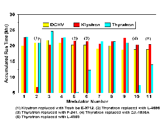
continuously except scheduled short-term shut downs. Fig.1 shows
the total accumulated times of klystron and thyratron heater operation,
and the high voltage run. Sum of the high voltage run time of
each modulator has reached over 230,000 hour, and the experience
accumulated so far provides the valuable information for the stable
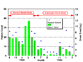
operation. Fig. 2 shows the monthly failure and down time statistics
for the period of September 1994 to May 1995(manual reset) and
the period of May 1995 to May 1996(auto reset).
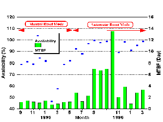
Machine availability analysis has been performed based on the data using the techniques described in detail in reference[3]. Fig.3 is the monthly availability and MTBF (mean time between failure) statistics of klystron-modulator system. The table 3. is the summary of the average fault analysis data. The MTBF calculated by dividing the sum of the accumulated modulator run time with the total fault count(MTBF=N*TO/FC). The MTTR(mean time to repair) is equal to the total down time divided by total fault counts (MTTR=TD/FC).
One can see in table 3, approximately 76% of the
machine availability(A=1-MTTR*FC/TO) has been improved to approximately
96% by applying auto reset mode operation with the simple CB trip
modification, which is also shown in Fig 2 & 3. It indicates
most of the system troubles are not so serious, and in many cases
they are easily recoverable.
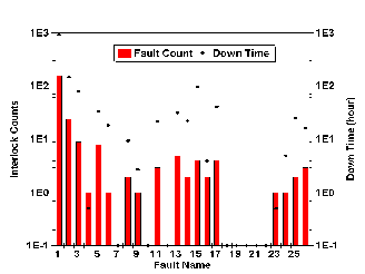
Table 3. Fault analysis of klystron-modulator system for PLS.
| Number of modulators, N | ||
| Spare no. of modulators | ||
| Operation time(hr)*1, TO | ||
| Total failure counts, FC | ||
| Total down time(hr) | ||
| MTBF(hr) | ||
| MTTR(hr/failure count) | ||
| System availability, A |
*1) Operation time for the statistical analysis.
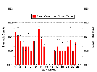
Fig. 4 shows the total systems static fault count
data collected during the period of September 1994 to May 1995.
Fig. 5 is the total system static fault count data collected for
the period of Jun 1995 to May 1996. From Fig. 4 & 5 one can
see the significant decrease in CB trip count by the CB trip modification
and the apparent relative increase in klystron troubles as the
accumulated run time increases.
It is approximately 2 years since the PLS 2 GeV linac
has started its operation. We have analyzed the klystron-modulator
systems performance record for the period. It is observed that
the reliability of klystron is well over our expectations compared
with other components in the modulators. The life time of thyratron
tubes appears to be reasonable except the occurrence of infant
failures. However, the major improvement is necessary for the
reservoir control which is the main source of system troubles.
The machine availability statistics of the K&M system for
the manual reset mode is calculated to be approximately 76%. It
appears to us that there are still lots of rooms for the improvement
toward the availability more than 96% with proper choices of the
protection circuits and the automatic reset mode. During the period
of Jun 1995 to May 1996 we have modified our OCR (over current
relay) interlock not to interrupt main CB but SCR gate(with static
fault action) as an attempt to reduce major source of static fault.
During the period no system damage has been occurred, and we have
activated remote reset control in the case of static fault. Just
one year old statistics shows an excellent system's availability
of approximately 96%.
This work is partially supported by POSCO (Pohang
Steel and Iron Co.) and Korea Ministry of Science and Technology.
[1] W. Namkung, "PLS 2 GeV Linac," Proc. 1994 Int'l Linac Conf., Tsukuba, Japan, Aug.21-26, pp.14-18(1994).
[2] M. H. Cho et. al, "High Power Microwave System for PLS 2 GeV Linac," Proc. 1994 Int'l Linac Conf., Tsukuba, Japan, Aug. 21-26, pp.418-420 (1994), M. H. Cho et. al, "Design of 200 MW Pulse Modulator for PLS 2 GeV Electron Linac," Proc. 3rd European Particle Accelerator Conf., Berlin, Germany, Vol.2,pp. 1591-1593 (1992).
[3] A. R. Donaldson and J. R. Ashton, "SLAC Modulator Operation and Reliability in the SLAC Era," IEEE Conf. Proc. 20th Power Modulator Symposium, pp.152-156 (1992).