Heavy ion inertial fusion (HIIF) injector linacs start with a set of low frequency radio-frequency quadrupoles (RFQs), because of the small values of the current limits of linear accelerators in the low energy part. For a higher ion energy, the frequency is increased to reach a better accelerator efficiency. The accumulation of ion beam current in such a driver linac is done by multiple stages of funneling: in each stage the accelerator frequency is doubled and two beams with 180 degrees phase shift are combined to fill all the rf-buckets of the high frequency accelerator stage. In the ideal case, there is no change of the emittance and the beam current and brightness are doubled.
For the first funneling stage a two-beam RFQ, where
two beams are bunched and accelerated in a single r.f. cavity
and a novel scheme for an rf funneling deflector operating at
low voltages has been developed. With the use of convergent beams,
a short funneling structure placed around the beam crossing position
seems to be possible.
A heavy ion inertial fusion (HIIF) driver could start
with a set of low frequency radio-frequency quadrupoles (RFQs)
which employs electrical r.f. focussing and provides bunched ion
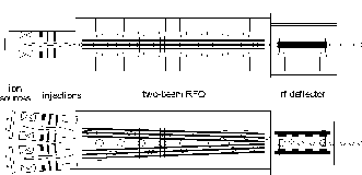
beams with high transmission[1,2]. The layout of a HIIF injector
is shown in Figure 1.

Initial funneling experiments have been done with
systems of discrete elements such as quadrupole doublets and triplets,
debunchers, deflectors and bending magnets [3,4,5]. Another solution
for beam funneling is the use of an accelerator structure which
provides two beams within one cavity and a single r.f. deflector
structure which bends the two beams to one common axis.
The two-beam RFQ consists of two sets of quadrupole
electrodes driven by one resonant structure. For this reason the
new two-beam RFQ brings the two beams very close together while
they are still radially and longitudinally focused. For the beam
funneling experiment an electrode geometry of the two-beam RFQ
that gives identical radial beam orientations is favourable. The
two possible electrode geometries are shown in Figure 2.

The electrode capacity should be as small as possible to achieve an efficient r.f. structure. Therefore the inner electrodes of the two quadrupoles have the identical r.f. phase. With such an electrode geometry a smaller beam separation and convergent beam axes have become possible. For the support of the chosen electrode geometry (Figure 2 b) an RFQ structure with symmetric stems from the bottom to the top of the cavity is taken to minimise the dipole effects.
To study the properties of the new two-beam RFQ resonator,
various kinds of prototype resonators were built and tested [6,7].
Also calculations with the MAFIA code were done for comparison
with the low level measurements. A prototype resonator with a
reduced length and parallel beam axis has been designed and built.
The resonator consists of two pairs of electrodes with a length
of 100 cm supported by four symmetric stems in linear arrangement.
In high power tests the maximum r.f. input power in pulsed mode
was limited to 12 kW by the r.f. power amplifier. At this
power an electrode voltage of 27 kV was measured. For the
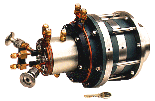
beam funneling experiments a two-beam RFQ 2 m long with convergent
beam axes is under construction. Figure 3 shows a view of
the two-beam RFQ.

The electrode geometry of the multigap deflector
consists of some deflector plates divided by spaces or sections
with larger aperture with equal length. In this geometry, the
particles will see the deflecting field in one direction several
times but the deflection in the opposite direction is always less.
The length of the capacitors have to be proportional to the particle
velocity and to the inverse of the frequency of the deflector
system. Figure 4 shows a scheme of the electrode geometry
and the behaviour of the particles along the multigap deflector.

For beam funneling, the frequency of the deflector
has to be the same as the accelerator frequency, so that the bunches
from different beam axes will see opposite field directions because
of the phase shift of 180° between each bunch. If the two
incoming beams are parallel, the cell length of the deflector
has to be ( = v/c with c = speed
of light and = wavelength of the deflector frequency)
to get a displacement only. If the two beams are not parallel,
the cell length has to be /2 to reach a maximum change
of the beam angle [8]. The r.f. resonator for the multi-gap deflector
will be a structure as it is used for 4-Rod-RFQs with two stems.
Each stem is electrically contacted with one of the deflector
electrodes and will sustain the other electrode by a ceramic support.
For longer electrodes it is possible to use an rf structure with
more stems to preserve mechanical stability. Figure 5 shows
a view of the multigap deflector.

The funneling experiments will be carried out with
He+ ions to facilitate ion source operation and beam
diagnostics. Two small multicusp ion sources and electrostatic
lenses, built by LBNL [9,10], will be used. A IGUN [11] simulation
of one lense is plotted in figure 6.

The ion sources and injection lens will be attached directly on the front of the RFQ with an angle of 76 mrad, the angle of the beam axes of the two-beam RFQ. Figure 7 shows a photograph of the multicusp ion source attached to the injection system.
With this angle of 76 mrad the distance between the two beams at the RFQ input will be more than 160 mm and about 40 mm at the output. The electrodes are supported by eight flat stems. To achieve a proper voltage distribution along the electrodes, the distance between the supports has to be reduced along the resonator. The RFQ electrode design is in progress with the use of the PARMTEQ code. For the phase shift of 180° between the bunches of each beam, two different electrode designs with different electrode lengths are required.

Behind the RFQ the funneling deflector will be placed
before the beam crossing. Figure 8 shows the experimental
set-up of the funneling experiment. Beam diagnostics in front
of and behind the RFQ and behind the funneling deflector are in
preparation. The funneling resonator is under construction and
a prototype for r.f. measurements has been finished.

In Table 1 the main parameters of the planned
experiment with He+ and the design parameters of a
first HIIF funneling stage for Bi+ are shown.
The experiments and results achieved by building
and evaluating the two-beam RFQ prototype resonators have provided
the needed knowledge to proceed with the final design of the two-beam
RFQ resonator for funneling. The MAFIA calculations for the RFQ
structure and the PARMTEQ calculations for the electrode design
are finished. A multigap deflector for funneling is under development.
A first deflector prototype for low level measurements has been
built. The ion sources and injection systems are manufactured
and are running on a test stand. Next steps are the assembly of
the experimental setup and the synchronisation of the two ion
sources.
[1] A. Schempp, A HIIF Funnel Injector System, GSI-Report, Gesellschaft f. Schwerionenforschung, GSI-95-06 (1995) p. 26.
[2] W. Barth, A. Schempp, Funneling Study with a Low Energy Proton Beam, Proc. PAC91, San Francisco, IEEE 91CH30387 (1991) p. 3076.
[3] K. Bongardt and D. Sanitz, Funneling of Heavy Ion Beams, Primary Report, Kernforschungszentrum Karlsruhe, 11 04 02P14C (September 1982).
[4] J.F. Stovall, F.W. Guy, R.H. Stokes and T.P. Wangler, Beam Funneling Studies at Los Alamos, Nucl. Instr, and Meth. A278 (1989) p. 143.
[5] K.F. Johnson, O.R. Sander, G.O. Bolmer, J.D. Gilpatrick, F.W. Guy, J.H. Marquardt, K. Saadatmand, D. Dandoval and V. Yuan, A Beam Funnel Demonstration: Experiment and Simulation, Part. Acc., Vols. 37-38 (1992) p. 261.
[6] A. Firjahn-Andersch, A. Schempp, C. Staschok and J. Madlung, A Two-Beam RFQ for Funneling of Ion Beams at Low Energies, GSI-Report, Gesellschaft f. Schwerionenforschung, GSI-95-06 (1995) p. 25.
[7] A. Firjahn-Andersch, A. Schempp, J. Madlung, C. Staschok, A Two-Beam RFQ for Funneling of Ion Beams at Low Energies, Proc. 1995 Int. Symp. on Heavy Ion Inertial Fusion, Princeton, USA, September 6 -9, 1995.
[8] J. Madlung, A. Schempp, A.Firjahn-Andersch, A Novel Design for Heavy Ion Beam Funneling, Proc. 1995 Int. Symp. on Heavy Ion Inertial Fusion, Princeton, USA, September 6 - 9, 1995
[9] K.N. Leung, Multicusp Ion Sources, Proc. 5th Int. Conf. on Ion Sources, Beijing, China, 1993, Rev. Sci. Instrum. 65(4), April 1994, p. 1165.
[10] R. Keller in: The Physics and Technology of Ion Sources, Edited by I. G. Brown, Wiley-Interscience Publication, New York
[11] R. Becker, W. B. Herrmannsfeldt, IGUN - A program
for the simulation of positive ion extraction including magnetic
fields, Proc. 4th Int. Conf. on Ion Sources, Bensheim, Germany,
1991, Rev. Sci. Instrum. 63(4), 1992, p. 2756.
* Work supported by the BMBF.