A Spiral-RFQ has been built and operated with Ar+-beams
up to 8 mA. In rf-tests very high electrode voltages were reached
at design duty factor. The aim of the experiments was the test
of the Spiral-RFQ for the High Current Injector (HSI), which is
planned at GSI to fill the Heavy Ion Synchrotron (SIS) up to its
space charge limit. This Spiral-RFQ, a prototype for the HSI-RFQ,
covers the crucial matching and bunching section of the electrodes.
It is capable to produce ion beams of high brilliance. The results
of recent beam experiments with Ar+ and rf-tests will
be presented together with work for future plasma physics experiments.
In 1990 the 18 Tm Heavy Ion Synchrotron SIS and the storage/cooler ring ESR went into operation. The linear accelerator UNILAC however, serving as injector for the SIS, had not been changed until then. To improve the UNILAC in a way of being able to fill the SIS up to its space charge limit several modification studies have been undertaken.
One possible solution is the combination of an ion source and a 27 MHz-Four-Rod-Spiral-RFQ with a length of 35 m, known as HSI (Hochstrominjektor) replacing the first Wideroe section of the UNILAC [1]. This RFQ should be capable to accelerate heavy ion beams of 25 mA U2+ from particle energies of 2.2 keV/u up to 216 keV/u. The particle charge would then be increased to U10+ by a gas stripper, further acceleration by the remaining second UNILAC Wideroe section would follow. At 1.4 MeV/u the ion charge would again be increased to U28+, and with postacceleration in the final UNILAC sections the beam would be ready for injection into the SIS.
Later studies deal with a layout for U4+
[2], where one stripper could be omitted. The RFQ-prototype could
well be used for these ions, too. For even higher performance
the rod-electrodes would simply have to be changed.
A prototype for the U2+-layout of the Spiral-RFQ has been built for both, rf-testing and beam experiments [3, 4]. It is only 4 m long but consists of the first 231 resonator cells, a third of the total HSI cell number. Nevertheless, the most critical part of the electrodes where the beam is matched and bunched is totally covered.
The resonator structure is mounted in a rectangular vacuum chamber made of aluminium. The structure itself can be easily accessed by eight lids in the side wall of the chamber. It consists of 20 spirally shaped copper stems; onto these the electrodes are mounted. The electrode alignment is achieved by precisely milled washers, it has been checked via an opto-mechanical system and is as precise as ± 0.1 mm, less than 3 % of the aperture radius.
Table 1 gives an overview on the main parameters
of the RFQ-prototype, Fig. 1 shows a schematic view of a 4-stem
Four-Rod-Spiral-RFQ structure.
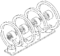
Fig. 1: Schematic view of a Four-Rod-Spiral-RFQ-Structure with four stems.
| Length | 3.95 [m] |
| Operating frequency | 27 [MHz] |
| Cell number | 231 |
| Input energy | 2.2 [keV/u] |
| Output energy | 17.6 [keV/u] |
| Synchronous phase | 39 [°] |
| Aperture radius | 6 [mm] |
| Max. electrode modulation | 1.458 |
| Normalized acceptance | 0.9 [·mm·mrad] |
| Electrode voltage | 1.51 · A/ [kV] |
| Rf-power consumption | 0.018 · A2/2 [kW] |
| Space charge limit | 0.2 · A/ [mA] (i.e. 8 [mA] Ar+ ) |
After having accelerated a He+-beam of 980 A at
the IAP Frankfurt (Institut für Angewandte
Physik) - however, due to a mismatched injection, at twice
the design rf-level - further beam tests with heavier ions were
done at GSI. The ion beam was extracted from a CHORDIS (Cold
or Hot Reflex Discharge Ion Source)
and focused for RFQ injection by one magnetic quadrupole doublet
lens and one magnetic quadrupole triplet lens. Therefore an optimized
matching could be achieved. For beam measurement three beam transformers
(behind the ion source, in front of and behind the RFQ), two fast
Faraday cups as well as an emittance measurement device were available.
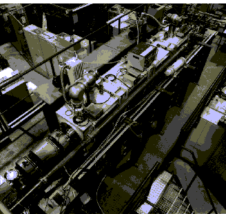
Fig. 2 shows a photograph of the experimental setup.
The quadrupole parameters of the injection system were optimized with numerical methods. The actual input beam quality could be observed by mounting an emittance measurement device in place of the RFQ. The results confirmed the computer simulation well.
With Ar+-ions a maximum pulse beam current of 8 mA could be reached at design-rf-level; this is the space charge limit for the RFQ calculated with PARMTEQ (Phase and Radial Motion in Tranverse Electric Quadrupoles) assuming ideal electric field distribution. The peak bunch current was 30 mA. Extrapolation to U2+-ions would lead to a pulse beam current of 24 mA (i. e. a peak bunch current of 90 mA). Fig. 3 shows the pulse beam current at RFQ input (upper) and RFQ output (lower); the scale is 2 mA/div. vertically and 1 ms/div. horizontally. The peak bunch current is shown in Fig. 4; the scale is 10 mA/div. vertically and 10 ns/div. horizontally.
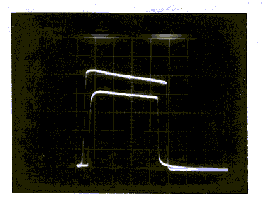
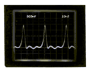
Fig. 4: Bunch current at RFQ output. The scale is 10 mA/div. vertically and 10 ns/div. horizontally.
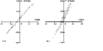
The measured transverse emittance was 50 ·mm·mrad,
the energy spread was ± 1.5 %, again well-corresponding
to computer simulations. Fig. 5 shows the output emittance
after 530 mm drift in the xx'-plane (left) and the
yy'-plane (right).
For accelerating ions with yet a higher mass-to-charge ratio higher
electrode voltages (and so rf-levels) are required. The ability
of the RFQ to operate under such conditions has been tested. After
a considerable time of conditioning the maximum applied rf-power
was as high as 260 kW at a duty-cycle of 0.4 % / 50 Hz.
The electrode voltage, measured with an rf-pickup probe calibrated
with Ar+-beam, was 185 kV. This leads to a very high
maximum field gradient of 340 kV/cm, corresponding to a Kilpatrick
value of about 3. The Rp-value (= shunt impedance) is 520 k·m,
which confirms previous low-level measurements [3]. The RFQ behaved
stable, no excessive sparking and no ponderomotive effects could
be observed. Adequate cooling of the RFQ-structure ensured that
the resonance frequency showed no drift. Higher rf-levels could
not be applied due to the limited rf-amplifier power.
Further use of the 27 MHz-Spiral-RFQ-Prototype will be providing a high-current He+-beam (0.8 mA) for experiments in plasma physics. The beam will be fed onto a luminescent target, allowing the bunch structure being observed with high time-resolution by a streak-camera. Another planned experiment is the interaction of the ion beam with thin plasmas for space charge neutralisation purposes.
The ion beam will be extracted from a CHORDIS source and will be injected into the Spiral-RFQ via two solenoid lenses. The final focus will be achieved by a magnetic quadrupole triplet lens. For beam current and bunch structure observation there are beam transformers and Faraday cups installed.
The work for setup of the experiment is almost completed so that
first beam measurements are scheduled for September 1996.
The objective of the recent experiments, proving the capability
of the Four-Rod-Spiral-RFQ serving as an injector providing highly
brilliant high-current heavy-ion beams, could be fully achieved.
Beam current as well as the rf-parameters were in very good correspondance
to PARMTEQ simulations. Therefore the Spiral-RFQ-prototype can
supply high-current ion-beams for experiments in plasma physics
as well as working as a compact implanter for singly charged heavy
ions like O+, P+, As+, up to
Kr+.