The separated sector cyclotron at the ISL (Ionen-Strahl-Labor,
Berlin) will get a new injector. The RFQ-part of the injector
consists of two closely coupled VE- (Variable Energy) RFQs with
an input energy range of 15 to 30 keV/n and an output energy range
of 90 to 360 keV/n. For direct injection into the cyclotron a
small energy spread and a duty factor of 100 % are needed, which
is difficult for RFQs. Calculated and measured rf-properties of
the RFQs will be discussed.
The scientific program at the ISL, the former VICKSI-
(Van de Graff Isochron Cyclotron Kombination für Schwere
Ionen) facility has changed from nuclear physics to solid state
physics [2]. The VICKSI-facility consists of two external injection
beamlines, a Van-de-Graff and a Tandem injector with a separated
sector cyclotron as postaccelerator. To meet the demands of the
solid state physics users the Tandem injector will be replaced
by a combination of an ECR source mounted on a 200 kV platform
and a two stage VE-RFQ. The ECR-RFQ-combination will accelerate
the ions to energies between 0.09 and 0.36 MeV/n to cover
the range of final energies out of the cyclotron between 1.5 and
6 MeV/n.
In an RFQ structure [3] the accelerating longitudinal
fields are achieved by a geometrical modulation of the quadrupole
electrodes, as shown in figure 1. The shape of the electrodes
is characterized by the parameters aperture radius a, modulation
m and the cell length L.

Due to the Wideroe resonance condition [4], where p is the normalized particle velocity, vp the particle velocity and f the frequency:
, (1)
the fixed particle velocity profile can only be varied by either changing the cell length or the frequency. The second possibility is the way which has been used for RFQs with variable energy [5]. For this reason it is possible to change the output energy Eout using the same electrode system: vpf, Eoutvp2.
To change the frequency of the 4-Rod RFQ, a type
of resonator developed in Frankfurt [6], the resonator can be
tuned capacitively or inductively. Figure 2 shows the inductive
tuning by a movable tuning plate, which varies the effective length
of the stems.

In Frankfurt the VE-RFQ was developed at first for the application as a cluster postaccelerator at the 0.5 MV Cockroft-Walton facility at the IPNL (Institut Physique Nucleaire Lyon, France) [7, 8]. This accelerator is designed for an input energy between Ein=5 keV/n and 10 keV/n and an output energy between Eout=50 keV/n and 100 keV/n.
Based on the positive experiences of this project,
a first combination of an ECR source with a VE-RFQ has been built
for the IKF (Institut für Kernphysik, Frankfurt). The RFQ
is designed for a minimum charge-to-mass-ratio of 0.15, an output
energy of Eout=100-200 keV/n, a maximum electrode
voltage of 70 kV and has a structure length of 1.5 m.
To inject into a cyclotron, the RFQ has to provide a bunched beam at a well defined injection energy determined by the inner radius of the cyclotron. The energy variability of the separated sector cyclotron will be kept by using an injector which has a variable energy and a variable frequency like the VE-RFQ. The operating frequency of the RFQs must be synchronized with the cyclotron frequency. RFQs have a fixed ratio of input to output energy given by the cell length of the first and last acceleration cell. This is similar to the energy gain factor of a cyclotron. For these reasons a VE-RFQ is well suited as an injector for a cyclotron [9].
The new injector consisting of an ECR source and a VE-RFQ has to fit into the existing Tandem beamline. To stretch the energy range of the injector the RFQ will be split into two RFQ stages, mounted in one vacuum-chamber. Each stage with a length of 1.5 m consists of a ten stem 4-Rod RFQ-structure. With a power consumption of 20 kW per stage an electrode voltage of 45 kV will be possible.
The RFQs will be driven in two different modes of
operation. In the high energy mode both RFQs accelerate, the output
energy of the cyclotron is between Eout=3 MeV/n
and Eout=6 MeV/n with a harmonic number
of 5 for the cyclotron. In the low energy mode the second RFQ
has a detuned phase and works as a quadrupole transport channel.
The energy range of the cyclotron in this mode is between Eout=1.5 MeV/n
and Eout=3 MeV/n. The cyclotron works on
the harmonic number 7. In both modes the frequency of the RFQ
is tuned to the eighth harmonic of the cyclotron frequency. Parameters
are given in table 1.
| RFQ: | |
| Cyclotron: | |
The RFQ output emittance depends largely on the input conditions. For matched input beams with an energy spread E/E 1.5 %, a normalized emittance n 0.5 mm mrad and a bunch length t 1 ns a transmission of 100 % is expected. To reach this beam quality it is necessary to have a buncher-chopper system between the ECR and the RFQs [10].
The ECR source is mounted on the 200 kV platform formerly used for the Tandem(see figure 3).

The vertical beam is bent by 90°, passes through
the buncher-chopper system and will be injected into the RFQs.
The final matching into RFQ1 will be done by a triplet
lens. The beam from RFQ2 is transported into the injection
beamline of the cyclotron, to which a rebuncher has been added
to make a proper time focus for the cyclotron.
The rf-properties were calculated with the code MAFIA
Ver. 3.2 [11], to check several structural details. The main point
of interest is the relation between the tuning plate position
and the frequency as well as the dependance of the shuntimpedance
and the Q-value on the frequency, as shown in figure 4.

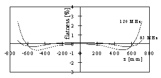
Another point of interest is the electrode voltage
along the RFQ (flatness), which should be constant. Calculations
have shown that the flatness is a function of the frequency. The
value of 3 % at the highest frequency is noncritical, at
lower frequencies it decreases, as shown in figure 5.

With MAFIA the loss distribution at the different RFQ-components has been calculated. Results show that 64 % of the power will be lost at the stems (at 85 MHz). At 120 MHz the losses are: electrodes 31 %, tuning plate 19 % and electrode supports 12 %.
The duty factor of 100 % and the maximum power consumption of 20 kW together with the calculated losses at the different components were the arguments for a modified electrode material with an integrated cooling channel.
To compensate the frequency shift caused by thermal
effects at high power level an additional tuning element is required.
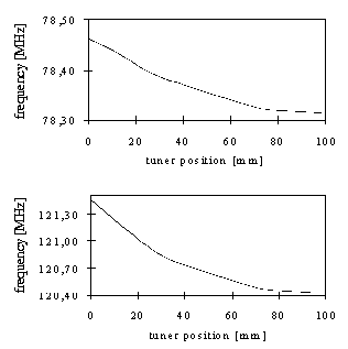
The effect of the slow tuner to the frequency varies with the
resonance frequency as shown in figure 6.

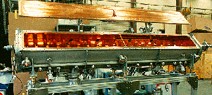
The vacuum chamber is copper plated and leak tested,
the stems are aligned and mounted in the cavity. The components
(tuning plate, vacuum pumps, etc.) are installed (figure 7).

The electrodes and their supports are manufactured and will be brazed together with the water cooling. First low level measurements are scheduled for September 1996, the high power tests at NTG will start in Oktober 1996.
[1] H. Homeyer, W. Pelzer, „Vorschlag zur Realisierung eines Ionenstrahllabors im HMI (ISL-Berlin)", HMI-Berlin, (1992).
[2] H. Homeyer, K. Ziegler, NIM B64 (1992) 937-942.
[3] K.R. Crandall, R.H. Stokes, T.P. Wangler, RF Quadrupole Beam Dynamic Design Studies, Linac 79, BNL 51134 (1979) 205.
[4] R. Wideröe, Archiv für Elektrotechnik 21 (1928) 387.
[5] A. Schempp, RFQ Ion Accelerator with Variable Energy, NIM B40/41 (1989) 937.
[6] A. Schempp, M. Ferch, H. Klein, PAC 87, IEEE 87CH2387-9 (1987) 267.
[7] A. Schempp, H. Moser, Acceleration of Cluster Ions to Energies up to 0.1 MeV/n, Journal de Physique, C2-50 (1989) 205.
[8] M.J. Gaillard et al., First High Energy Hydrogen Cluster Beams; A New Facility at IPN Lyon, France, Z. f. Phys. D26 (1993) 347.
[9] A. Schempp, Beiträge zur Entwicklung der Radiofrequenzquadrupol(RFQ)Ionenbeschleuniger, Univ. Frankfurt/ M, Habilitationsschrift 1990.
[10] W. Pelzer, K. Ziegler, Atomenergie Kerntechnik Vol. 46-3 (1985) 147.
[11] T. Weiland, Computer Modelling of two- and three-dimensional cavities, IEEE NS-32 (1985) 2738.
Neue Technologien, Im Steinigen Graben 12-14,
63571 Gelnhausen
* Work supported by the BMBF.