The front end of the ESS Linac has to provide a bunched high current H--beam with a special time structure for injection into the following DTL. This can be achieved by a system of two 175 MHz RFQ lines, each with a current of 54 mA, whose beams will be combined in a funnel section to a 107 mA beam with a bunch repetition rate of 350 MHz. For a proper operation of the compressor rings the linac beam must be chopped with a 60% duty factor at the ring revolution frequency of 1.67 MHz which implies beam pulses of 360 ns and gaps of 240 ns during the macro pulse of 1.2 ms. A layout of the chopping line will be presented. A new concept for beam funneling using a two-beam RFQ and a multigap funneling deflector will be discused.
The RFQ (Radio Frequency Quadrupole) injector for the ESS linac provides a bunched beam of 107 mA at 5 MeV. This will be achieved by a system of two 175 MHz RFQ lines, each with a current of 54 mA, whose beams will be combined in a funnel section. For proper operation of the compressor rings the linac beam must be chopped with a 60% duty factor at the ring revolution frequency of 1.67 MHz which implies beam pulses of 360 ns and gaps of 240 ns during the macro pulse of 1.2 ms. The chopping system shall also be used to achieve sharp edges at the head and the end of the macropulse.
Each RFQ line is split into two sections with the chopping line between the two RFQs to enable chopping with an unneutralised, bunched beam at a moderate energy to reduce the required chopping voltages but at an energy high enough so that the beam can be transported through the line with a minimum emittance growth. Figure 1 shows a schematic drawing of the ESS RFQ injector system.

The design of the first RFQ has been optimised for a total normalised input emittance of 1 p mm mrad with respect to a small output emittance and a reduced output divergence of the beam to match to the chopping line. The operating frequency of the RFQs will be 175 MHz in order to be well below the current limit. In Table 1, the main parameters of the ESS RFQs are shown.
| f0 [MHZ] | ||
| Ein [MeV] | ||
| Eout [MeV] | ||
| Length [m] | ||
| Ncav [kw] | ||
| Nbeam [kw] |
A fast beam chopper has to be included into the injector to create voids for a loss free extraction from the compressor rings. In addition the head and the tails of the macro bunches could be cut away, where the beam intensity may vary due to space charge neutralisation effects. In the EHF-proposal [1] the layout of such a chopping line was presented, which could be adapted to the ESS requirements in a first step. Beam dynamics calculations showed high transmission (< 95%) at a transverse emittance growth of 50%. The bunch width could be kept smaller than ±45° [2]. Never-theless the length of the line is about 7 m and the transverse beam dimensions become inbetween rather large, therefore the investigation of a more compact line has been started [3].
The chopping line has been designed with the chopper and the beam dump placed in the same drift section. It consists of single quadrupoles and buncher cavities. The beam dump will be in front of the third buncher cavity, where enough space for cooling is available. A drawing of the chopping line is shown in Figure 2.

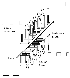
The chopper structure will be a pulsed electrostatic deflector, based on the BNL design [4], with deflection plates segmented into strips transversal to the beam direction. They are connected by coaxial delay lines, so that the pulse velocity along the beam direction is matched to the beam velocity. One set of strips above and below the beam will halve the magnitude of the voltage needed for deflection. A drawing of the chopper structure is shown in Figure 3.
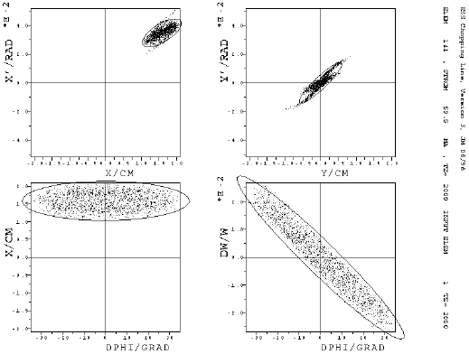
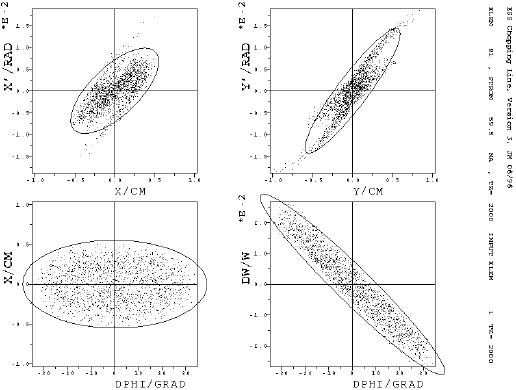
The output distribution of RFQ 1 (which is the input for the chopping line) and the output of the chopping line are shown in Figure 4 and Figure 5.
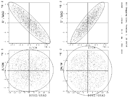
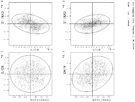
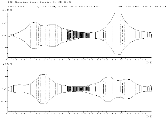
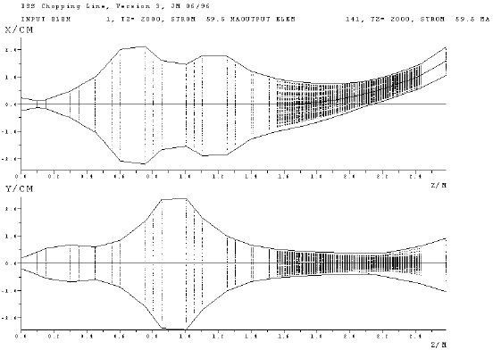
To avoid that bunches at the head or the end of the macropulse are not totally filled, the chopping voltage must rise in less then one rf-cycle. So the rise and fall time of the chopping voltage of 2 kV has to be less than 4.5 ns to achieve a clean chopping and this seems to be within technical possibilities. Beam dynamics calculations for this layout have been done with the PARMTRA-code using an rz-Poisson-solver and a beam current of 59.5 mA. The results show a transmission of 99% through the chopping line. The separation of the chopped and the unchopped beam at the position of the beam dump is about 5 mm. Figure 6 shows the transversal behaviour of the unchopped and Figure 7 of the chopped beam along the chopping line. The particle distributions both for the chopped and unchopped beam at the position of the beam dump are plotted in Figure 8 and Figure 9.
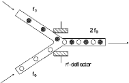
To achieve the required beam current of 107 mA two identically bunched beams have to be combined into a single beam with twice the frequency, current and brightness. This so called funneling, proposed first by Montague and Bongardt [5], has to be done with a well bunched beam, which is needed for low emittance growth in a system of dipoles, quadrupoles, rebunchers and a deflector. Figure 10 shows the principle of funneling.
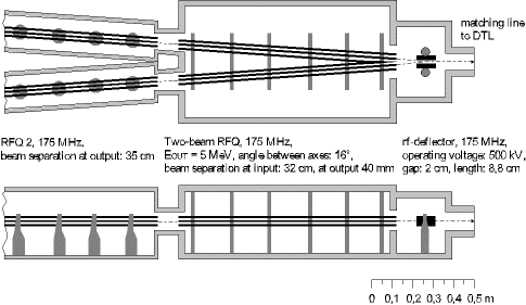
Now a new system with a two-beam RFQ and a resonator driven deflector has been investigated. A first two-beam funneling experiment includes a two-beam RFQ where the beams are bunched and accelerated with a phase shift of 180_ between each bunch. In the two-beam RFQ the beam separation is kept small. Therefore the rf-funneling deflector system can operate at low voltages. The new concept, based on a resonator driven multi-gap deflector, where the ions are deflected several times, facilitates some constraints in beam funneling like the limitation of the electric field by rf-sparking. To study the properties of the new two-beam RFQ, different types of prototype resonators were built and tested. Also calculations with the electrodynamics CAD program MAFIA have been done for comparison with the low-level measurements. A combination of a two-beam RFQ, which joins the two separated RFQ 2-resonators, and a single- or multi-gap deflector will be used for the ESS linac. Figure 11 shows a scheme of the ESS funneling section and Table 2 the main parameters of the two-beam RFQ and the rf-deflector.
| two-beam RFQ | |
| f0 [Mhz] | |
| Ein [MeV] | |
| Eout [MeV] | |
| Length [m] | |
| Ncav [kw] | |
| Angle between beam axes [mard] | |
| rf-deflector | |
| f0 [Mhz] | |
| Voltage [kV] | |
| Length [cm] | |
| Ncav [kw] | |
| Beam separation at input [mm] |
[1] Proposal for a European Hadron Facility, Editor: J.F. Crawford, EHF-87-18 (1987).
[2] H. Deitinghoff, G. Parisi, A. Sauer, Adaption of the EHF Low Energy Transfer Line to ESS Requirements, Int.-Rep. 96-5, IAP Frankfurt (1996).
[3] J. Madlung, A. Firjahn-Andersch, A. Schempp, Chopping- and Funneling Studies for ESS at Frankfurt, PSI-Proceedings 95-02 (1995) p. 736.
[4] J.M. Brennan, et al., A Fast Chopper for Programmed Population of the Longitudinal Phase Space of the AGS, BNL-41832, PAC89, IEEE CH2669 (1989) p. 1154.
[5] K. Bongardt, D. Sanitz, Funneling of Heavy Ion Beams, Primary Report, Kernforschungszentrum Karlsruhe, 11 04 02P14C (1982).