The Argonne Wakefield Accelerator (AWA) facility
has begun its experimental program. This unique facility is designed
to address advanced acceleration research which requires very
short, intense electron bunches. The facility incorporates two
photo-cathode based electron sources. One produces up to 100 nC,
multi-kiloamp 'drive' bunches which are used to excite wakefields
in dielectric loaded structures and in plasma. The second source
produces much lower intensity 'witness' pulses which are used
to probe the fields produced by the drive. The drive and witness
pulses can be precisely timed as well as laterally positioned
with respect to each other. We discuss commissioning, initial
experiments, and outline plans for a proposed 1 GeV demonstration
accelerator.
The generation of high gradients (> 100 MV/m) in wakefield structures requires a short pulse, high intensity electron drive beam. The main technological challenge of the AWA program is the development of a photo injector capable of fulfilling these requirements. The goal of the AWA is to demonstrate high gradient and sustained acceleration of charged particle beam by using wakefield method. In the past year we have made considerable progress towards attaining the design goals of the AWA.
Fig.1 shows the schematic diagram of the AWA facility,
consisting of 3 major components: 1) an L-band rf photocathode
and Linac capable of producing a 100 nC electron drive beam; 2)
a second L-Band photocathode gun generates a low emittance and
low charge beam which probes the wakefield produced by the intense
drive beam and 3) An experimental test section for wakefield experiments.
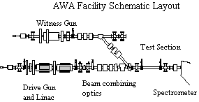
A picosecond UV laser with up to 8 mJ/pulse output is used to illuminate the photocathode for both guns.
In this paper we present detailed descriptions of
the facility and initial characterization of its performance.
The preliminary results of dielectric and plasma wakefield experiments
are discussed. The near and long term plans for experiments and
facility upgrades will be described.
The gun and drive linac are shown in Fig. 2. The laser photocathode sources was designed to deliver 100 nC bunches at 2 MeV to the drive linac. The photocathode gun is a single cell standing wave cavity with designed peak field of 90 MV/m on the cathode [1]. Some of the novel features incorporated into the gun to attain high intensities include a large (2 cm diameter) cathode, the use of a curved laser wave front and nonlinear focusing solenoids matched to the angle-energy correlation computed for the 100 nC bunch. So far, only flat laser pulses have been used for the experiment. However, for most AWA experiments, only 40 ~ 60 nC pulses are needed as discussed below.
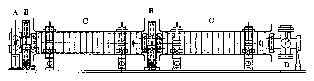
The AWA drive linac [2] consists of two sections
of /2 standing wave structures. Each section is about a meter
long. The linac is designed to deliver 18 MeV electron beam with
5 ~ 10 % of energy spread at 100 nC.
The witness gun a six-cell, copper, iris loaded, rf photocathode operating at 1.3 GHz in a p/2 standing wave mode. A low charge, low emittance witness beam (0.1 nC charge, 1 p mm-mrad 90% physical emittance) is produced to probe (i.e. witness) the wakefields left behind by the drive beam . The witness gun is a scaled down version of the s-band Mark IV accelerator that was used at SLAC, as described in reference [3]. Since the Mark IV Accelerator was a linac, some adjustments were made to turn it into a photocathode gun using the rf design code URMEL. The witness gun has a photocathode in the first 1/2 cell, a coupling iris in the fourth full cell and a beam exit hole in the last half cell.
In order to probe the test devices properly, the
witness beam must have a kinetic energy of 4 MeV, a physical emittance
of 1 p mm-mrad, an energy spread of less than 1% and a bunch length
of about 5 ps. Extensive simulations with PARMELA have shown the
Mark IV type gun to be capable of achieving the design parameters.
Using a 1.5 mm spot size and a phase launch of 65 degrees we obtain
the following results
| Energy | 90% Emittance | Energy Spread | Bunch Length |
| 4.53 MeV | 0.76 p mmmrad | 0.5% FW | 5.6 psec |
The picosecond KrF laser system
The laser consists of a front end that produces picosecond pulses at 248 nm and a final KrF amplifier. The central component of the front end is a synchronously pumped mode locked dye oscillator (Coherent 702). The dye laser is tuned to the desired wavelength of 497 nm by a single-plate birefringence filter. Coumarin 102 dissolved in benzyl alcohol and ethylene glycol is the lasing medium, and DOCI dissolved in benzyl alcohol and ethylene glycol is the saturable absorber. A harmonic tripled mode locked Nd:YAG laser is used to pump the dye laser. The frequency of the mode locker is 40.625 MHz of which the 32nd harmonic is exactly 1.3 GHz.
A single pulse from the dye laser output train is amplified to 300 µJ through a three-stage amplifier. The dye amplifier is Lambda-Physik FL2003 pumped by 100 mJ, 308 nm pulses from a Lambda-Phyisk LPX105i excimer laser. The duration of the pump pulse is shortened to 10 ns so only one pulse from the dye oscillator can be amplified. The output from the dye amplifier is frequency doubled in a 3x3x7mm angle matched BBO crystal. Output at 248 nm is typically 25 - 30 µJ. Because the length of this doubling crystal, temporal broadening of the input pulse is expected.
Amplification of the ultra-short UV pulses is done in a single stage KrF excimer laser (Lambda-Physik LPX105i). The input pulses pass through the amplifier twice in order to fully utilize its stored energy. Typical output of 8 - 10 mJ is obtained routinely. The length of the final pulse is measured by Hamamatsu streak camera (model C1587) which has resolution of 2 ps. The typical measured pulse length (FWHM) is 3 - 4 ps. No satellite pulses observed. Repetition rate of the of the laser can be as high as 35 Hz.
In order to have certain flexibility of the experiment,
we can run the Coherent 702 dye laser in a single jet mode. In
the single jet mode, the laser is capable of producing pulse length
from 5 ps to 30 ps. We have verified the laser pules length by
using the autocorrealtor and streak camera. The laser energy is
from 5 - 7 mJ/pulse with nominal fluctuation of 10% for the long
laser pulses..
Controls and data acquisition
The design of the AWA control system[6] is based in part on the experience gained at the Advanced Accelerator Test facility (AATF), and also on more extensive data acquisition systems used for high energy physics experiments. The goal of the AWA system is to provide easy selection and adjustment of accelerator and beamline parameters, as well as the online analysis of diagnostic and physics data.
At the core of the system is an HP-750 RISC workstation
using the UNIX operating system. The workstation is interfaced
to VMEbus via a high speed adapter with dual port RAM. A 68060
CPU board on the VMEbus handles command requests from the workstation
and provides auxiliary processing capabilities. Most of the control
and monitoring functions are handled through a VME-CAMAC parallel
bus interface. Video signals from beam position monitors and from
the streak camera, comprising the actual physics data from the
experiment, are acquired using a high resolution VME-based frame
grabber. The AWA control software was developed in house and is
based on the Tcl/Tk scripting language. The various codes comprising
the system are written in C and FORTRAN77.
Detailed characterization of the both AWA drive and witness beam is currently underway. We have made an initial measurement of the beam properties at the exit of the Linac. Attempts were made to measure the pulse length and emittance vs the charge.
One unexpected problem encountered during the experiment was the low observed quantum efficiency of Magnesium photocathode, compared to measurements reported in the literature [4]. The QE found for Mg is 1~ 1.5x10⁻⁴. Hence almost all the available laser energy is required to generate a 100 nC beam. However, a higher intensity laser pulse generally induces the photocathode to emit electron continuously ("explosive mode") [5]. Therefore, our initial measurements were made with charges generally less than 100 nC.
A diagnostic port at the exit of the Linac consists
of an insertable pepper pot and a phosphor screen for emittance
measurements. A calibrated integrated current transformer (ICT)
device is used here for online nondestructive charge monitoring
and a thin quartz (1 mm thick) plate is used as a Cherenkov radiator
for pulse length measurement.
High Charge Generation
A 20-27 nC beam can be produced by 1 mJ laser pulse
regardless the laser pulse length. It appears that we run into
the space charge limit when we increase the laser power to 2 -
3mJ for short laser (5 ps). The maximum charge produced is 55
nC with 5 mJ of laser power. Increasing the laser pulse length
resulted in higher charges as expected. A 100nC per pulse were
observed, and 90nC pulses can be reached consistently with 5mJ
laser power
Pulse Length Measurement
The electron pulse length is measured by using a streak camera situated in the laser room. The Cherenkov light from the quartz plate in the diagnostic port is collected and transported to the laser room. The Cherenkov light transport line was carefully built to ensure that no electron beam information can be lost.
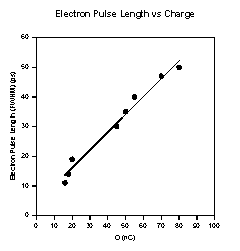
Results of the measurement are summarized in Figure
4. Because the electron pulse is not a gaussian, all the data
were characterized by the full width half maximum (FWHM). The
bunch length has a strong dependence on the charge. The shortest
bunch length is 11 ps for 18 nC beam. At each charge, we average
several data points to minimize the "random error" due
to the pulse to pelse charge fluctuations. For 80 nC beam (with
long laser pulse length), the measured electron pulse length is
48 ps, longer than the design goal (100 nC, 30ps). We are in the
process of setting up an experiment for further investigation
to attempt to reduce the bunch length. Note that while the Linac
focusing is optimized for the curved laser bunch, only planar
wavefront laser beam have been used
Emittance Measurement
A "pepper pot" with 0.5 mm holes and 2.5 mm spacing with a phosphor plate placed 40 cm downstream used for emittance measurement. Because of the small electron beam spot and relatively large holes of the pepper pot, and the resolution is about 10 mm mrad. Therefore, we have only estimated an upper limit on the emittance.
The following table summarizes the results of several measurements.
| Charge | Measured rms physical emittance |
| 20nC | 10 mm mrad |
| 55nC | 13 mm mrad |
| 70nC | 20 mm mrad |
The Witness Beam
The witness gun and its associated beam lines were
recently installed and commissioned. Properties of the witness
beam are being studied. The charge produced in the witness gun
ranges from 0.1 ~ 3 nC. The beam energy is 4 MeV. The beam has
been used for the initial dielectric wakefield measurements. Emittance
measurements using a quadrupole scan technique and bunch length
measurements using Cherenkov radiation are underway.
Synchronization of the drive and witness beam
Once the drive beam and the witness beam are generated,
both beams are transported to the experimental section and combined.
Since both the drive and witness beam are generated using the
same laser pulse, a laser beam splitter is used to reflect a small
amount of the laser beam through an adjustable delayed. Time delay
between the two beams can be adjusted precisely using a mirror
mounted on a movable stage for the witness laser beam line, while
at the sametime, adjusting the rf phase to the witness gun to
maintain a constant laser injection phase. The typical delay range
used in the wakefield experiments is -50 ps to 400 ps. Delays
up to 10 ns are possible using this system limited only by the
adjustable stage.
Initial Wakefield Experiment Results
We have performed several collinear wakefield experiments
to verify the performance of the AWA facility. Initial choice
of the wakefield device were dielectric structure fabricated from
Borosilicate glass. This material has a sufficiently large DC
conductivity to minimize charging effects during beam tuning when
scraping of the drive beam is worst.
Dielectric Wakefield Experiment
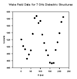
We have measured the wake field in two different dielectric structures (7 and 15 GHz). The results for the 7 GHz structure are shown in Figure 4. The wake amplitude is 1.5 MV/m for 20 nC drive beam. The structure has an inner radius of 1.25 cm and an outer radius of 1.6 cm with dielectric constant of 4. The measured wakefield amplitude and frequencies agree well the theory. This directly tested all the components of the AWA facility, and the results are satisfactory.
Another dielectric tube with inner radius 5 mm and outer radius 7.7 mm was also studied in the wakefield experiments. The resonant frequency for this tube is 15 GHz. A wakefield amplitude of > 5 MV/m was observed. Further tuning of the drive beam (more charge and shorter pulse length) should produce a wakefield in the excess of 15 MV/m in this structure.
Plasma Wakefield Acceleration and Focusing
Experiment
In collaboration with an UCLA group, we have performed
several preliminary experiments to study the plasma wakefield
acceleration in the blowout regime. The first set of experiments
demonstrated acceleration of a witness beam as a result of the
plasma wave excitation caused by the drive beam. There is a current
effort to study the self focusing of the drive beam. In order
for the drive beam energy to be optimally coupled to the plasma
wave, the drive beam must be focused to a very small spot, and
the radius of a significant part of the beam must be kept nearly
constant by the plasma's focusing force for the length of the
plasma. The aim of the current experiment is to quantify this
focusing and propagation, which depends greatly on the beam's
emittance, charge and initial matching, as well as on the plasma
properties.
Near term plans
a). Fully characterize the AWA beams, particularly the drive beam. Studying the beam properties (bunch length and emittance vs charge) dependence on the machine parameters.
b). High gradient collinear wakefield experiments using a dielectric structures. Generation of a electron pulse train and test the step-up transformer concepts. Ultimately to test the dielectric breakdown of the dielectric materials.
c). Continuation of nonlinear plasma focusing and acceleration experiments.
d). Colinear Wakefield Plasma Experiment. This experiment
will be very similar to the AATF experiment [6]. Since the drive
beam charge from the AWA is much higher than the charge from AATF,
one should expect much more intense wakefield. Although this experiment
will be in the non-blowout regime, we still believe it is very
interesting. We can scan the charge from 2 nC ~ 40 nC in the range
of plasma densities of 1012 ~ 5x10¹³. The
justification of this experiment is that although PWFA has been
a subject of the intense theoretical investigations, no one has
experimentally studied PWFA in detail. Since we have the capability
of mapping out the wakefields, this experiment should be straightforward
to carry out. The expected acceleration gradient produced in the
plasma would be in the range of 10 - 50 MV/m.
Long term plan
Its well know that a major constraint of collinear
wakefield acceleration is the transformer ratio. To overcome this
difficulty, an accelerating field step-up transformer scheme of
the dielectric wakefield accelerator was proposed[7]. The approach
is to extract rf power from an intense drive beam traveling in
a relatively large diameter dielectric wake field tube (stage
I). This power is then transferred to a smaller diameter dielectric
loaded guide (stage II) where the enhanced axial electric field
is used to accelerate electrons. Field enhancement results both
from a lower group velocity in stage II than in stage I ( longitudinal
compression), and from geometrical effects made possible by the
use of the dielectric loaded guide (transverse compression). High
net acceleration can be realized if one uses a train of large
number (10 - 20) electron pulses. The spacing of the drive pulses
can be arranged in such way that a long rf pulse is generated
to fill stage II. This also permits us to identify less stringent
parameters for the drive beam than previously described. Using
this new procedure we predict that Phase-I of the AWA (20 MeV
drive beam) can accelerate a witness beam to over 100 MeV in a
meter or less.
The current plans for the AWA (phase I) is to generate
40 nC, 20 ps long electron pulse train consisting of 10 -20 pulses.
Further upgrade of the drive beam energy in excess of 100 MeV
(phase II) without changing any of other parameters would enable
us to achieve net acceleration of the witness beam to 1 GeV energy
in a less of 10 meters. Therefore, successful demonstration of
the multiple pulse driven step-up transformer is critical.
Installation of the AWA Phase I facility has been
completed. The facility was successfully commissioned. The drive
gun and Linac has produced up to 100 nC beam with maximum pulse
length of 50 ps (FWHM). The witness gun has produced high quality
beams being used for the wakefield experiments. More detailed
characterizations of both beams are currently underway. Initial
collinear dielectric wakefield experiments verified the new wakefield
measurement system. High gradient wakefield acceleration experiments
in dielectric structures and in plasma are being pursued.
We would like to thank L. Balka, A. Caired, C. Keyser,
B. Taylor and K. Wood for their technical support. This work is
supported by the Department of Energy, Division of the High Energy
Physics, Contact No. W-31-109-ENG-38.
[1]. C. H. Ho, PhD Thesis, UCLA, 1992
[2]. E. Chojnacki et al.,Proceedings of the 1993 IEEE Paricle Accelerator Conference, pp 815-817.
[3] The Stanford Two-Mile Accelerator, (Chapter 6)
[4] T. Srinivasan-Rao et al., J. Appl. Phys 69 (5), 1991 p.3291
[5] X. J. Wang, PhD Thesis, UCLA, 1992
[6] J. Rosenzweig et al, Phys. Rev. Lett. 61, p 98, 1988
[7] E. Chojnacki, Proceedings of Particle Accelerator Conference, San Francisco, May 6-9, 1991, p2557-2559.