The state of the art of superconducting radio frequency
structures for particle acceleration is shown, with special reference
to the suitability of the available technology for high current
linear accelerators. It will be demonstrated that the basic requirements
for these applications can be met today and the limitations will
be discussed.
The pioneering work for the application of superconducting (SC) radio frequency (RF) accelerating structures in accelerators was done at Stanford with an electron recirculating machine [1]. Since then many projects have been realized and have shown the feasibility of SC RF. Prime examples were apart from the mentioned machine, the heavy ion accelerators at Argonne [2] and at Saclay [3]. Many of these machines have worked for several years and have paved the way for a wider use of SC RF in high energy accelerators. For electron acceleration, SC structures were used for S-DALINAC [4] and in the past years SC cavities have been successfully installed and used in large electron storage rings in the TRISTAN collider at KEK [5], and HERA [6] at DESY. The two biggest SC installations today are the recirculating electron accelerator CEBAF [7] with 169 m, and LEP2 with presently 245 m of active length installed. LEP upgrading will be completed in 1998 with 272 SC cavities covering an active length of 462 m, and giving nominally 2.7 GV.
In the past the main arguments for using SC cavities were the low RF losses, allowing a "cheap" RF installation. This is exploited particularly for heavy ion accelerators.
SC RF allows higher gradients to be achieved at reasonable RF power than normal conducting (NC) structures. This was first used in TRISTAN, then HERA, CEBAF and now in LEP. The upgrade of LEP with additional copper cavities is not possible merely because of space and prohibitive electricity cost, not to mention the large transverse impedance, which would severely limit the current.
The high gradient application is being intensely explored for large number production by TESLA[8], where 20 km of SC structures running at 25 MV/m will be required.
Recently new applications emerged for high current storage rings. One example is the upgrade of CESR [9], where SC cavities allow the transverse impedance to be kept minimal due to the small number of cavities with a large beam aperture, running at high gradient of up to 10 MV/m. Work is also going on at KEK for KEKB [10], where beam currents above 1 A are planned. A single cell cavity has been tested up to 11.7 MV/m.
The high stored energy in SC cavities is exploited in several applications: The extreme of beam loading is being studied for CLIC, where the high stored energy of SC resonators is used to accelerate the very intense bunches of the drive beam, about 50 % of the stored energy is taken by each pulse [11]. The acceleration system for LHC [12] with its circulating proton beam of 0.5 A, is based on SC cavities, mainly for reasons of stored energy.
A new field is presently being studied with growing interest: The use of SC cavities in high current linear accelerators for neutron sources, nuclear waste transmutation, accelerator driven reactors, etc. in the 1-1.5 GeV range [13-16].
This paper summarizes the state of the art in superconducting
structures, especially results obtained in series production,
and performance in accelerator operation. It will be shown that
many components required for high intensity linacs are already
available and limitations will be discussed.
2.1. Losses
A very important feature of RF superconductivity is the fact that even in the superconducting state, the surface resistance does not vanish. The unloaded Q-value Q0 of any cavity is proportional to 1/Rs ,where Rs is the surface resistance of the material. Rs of SC cavities is given by [17]:
![]() (1)
(1)
where T is the operating temperature, f the RF frequency, Tc the critical temperature (for Nb 9.2 K, for Pb 7.2 K) and A is a material dependent constant which is about 2.5*10-24 for Nb. For frequencies below 10 GHz a is near 1.85.
The first part is given by the BCS theory, the second part, the residual resistance RRES depends on the state of the surface, material impurities, etc.
The operating temperature has to be chosen as a function of frequency
and acceptable cryogenic losses. As (1) shows, the BCS part of
Rs increases with frequency, therefore a lower
operating temperature is desirable for high frequencies. This
has to be weighed against the efficiency of cryogenic cooling
plants. For the 12 kW plants at LEP a power factor of 225 W at
room temperature per W at 4.5 K has been measured [18], for 1.8
K operation 1 kW per W can be expected [19]. For LEP2 cavities
at 352 MHz, 4.5K operation is adequate, CEBAF cavities operating
at 1.5 GHz are cooled to 2K. Usable Q-values at nominal fields
are typically 1-5*109 for Nb cavities, for Pb they
are about a factor 10 lower.
2.2. Limitations
The theoretical limitation of accelerating field, given by the critical magnetic field strength is 50 MV/m for typical Nb high beta structures and 30 MV/m for quarter wave resonators [20]. In practice other factors limit the performance below these values:
Q-degradations leading to increased power deposition into the He can be caused by: trapped magnetic fields, surface defects and contaminations, local hot spots, which might even lead to a quench.
As an example, a curve of unloaded Q0 as a function
of accelerating field measured on a sputter coated Cu/Nb LEP cavity
is shown in fig. 1.
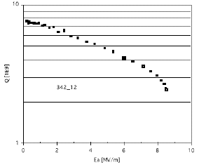
The design parameters for LEP are a Q0-value
of 3.4*109 at the nominal accelerating field of 6 MV/m.
The drop in Q in this case at 7.5 MV/m is attributed to the onset
of field emission. The operating field is chosen below this field
with some safety margin. Many cavities produced show no such field
emission up to above 8 MV/m.
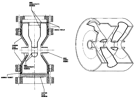
This is a very busy field of research and development. A comprehensive review is given by [21]. Modern applications mainly concentrate on coaxial resonators of the quarter- or half-wave length type with the beam passing on a diameter. So far, most work was directed towards applications with very low (µA) beam currents. In Argonne resonators were developed for high current (80 mA), high brightness ion beams, which went as far as cold RF testing of the resonators. In a half wave resonator made for a beta of 0.12, accelerating fields of 18 MV/m were achieved in cw operation at 355 MHz, (with some electron loading). The energy gain was 1.26 MV. Other prototype resonators for this purpose were developed and tested, a quarter wave resonator at 400 MHz and a "spoke resonator" operating at 850 MHz. Two examples are shown in fig. 2.
For the International Fusion Materials Irradiation
Facility (IFMIF) deuteron acceleration modules for 125 mA from
8 to 40 MeV (beta 0.06 to 0.14) are being studied using l/2
resonators [14].
Quarter wave structures operating at ATLAS provide gradients of up to 6 MV/m for low beta.
All these devices have only been operated with low
RF power. For a beam current of 100 mA, a synchronous phase of
20 degrees from the crest, the above mentioned resonator would
transfer 118 kW per structure to the beam, a value which is well
within the reach of power couplers today. High power operation
and vibration problems still need to be studied.
4.1. Structures
All high beta accelerators being conceived today make use of the elliptical cell shape as shown in fig. 3 in the case of LEP, with small modifications.
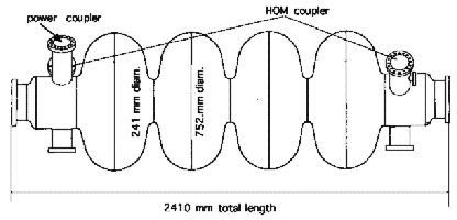
Usually several cells are coupled together via the beam aperture and operated in '-mode. This structure type is chosen because it is basically free of multipactor. The number of cells per cavity varies: for the CESR upgrading single cells (500 MHz) are chosen, the LEP2 (352 MHz) and HERA (500 MHz) cavities have 4 cells, TRISTAN uses 5 cells (500 MHz). Tuning is always done by elastic longitudinal deformation.
For lower beta acceleration development is going
on in Wuppertal for [13], where the same elliptical shape is being
studied for acceleration of particles in the range of beta from
0.37 to 0.91. These cavities have 5 cells of 1/2*b*l
length, a design field of 10 MV/m and a frequency of 700
MHz. Their r/Q values have been calculated to vary from 86 to
539 W/cavity.
A detailed mechanical design is still to be done, and the multipacting
properties need to be checked. Similar work is being done in Los
Alamos [15].
4.2 Performance in large scale applications
Large scale experience only exists with structures for beta=1. The operational parameters used in accelerators are:
TRISTAN: 32 5-cell cavities are installed (508 MHz), max. average gradient in operation: 4.7 MV/m, typical operating gradient: 3-3.8 MV/m
HERA: 16 4-cell cavities installed (500 MHz), usable gradient > 4 MV/m, power limited to < 100 kW/cavity, typically running at 2.6 MV/m presently.
CEBAF: 338 5-cell cavities, (1500 MHz), total active length 169 m, gradient > 5 MV/m average, wide distribution of cavity performance with peak of distribution at 7 MV/m, some cavities go as high as 14 MV/m
LEP2: Presently 144 4-cell cavities installed, (352 MHz), total active length presently 245 m, operating gradient: 5.5-6 MV/m. All 272 cavities will be installed by 1998.
SC RF technology in large scale accelerator applications
is very well established today.
5.1. Cavities and cryostats
High beta cavities are made of sheet material, half shells are spun and electron beam welded together. Two technologies exist: solid Nb and Nb sputtered in a thin film onto a copper substrate. The latter was developed at CERN and is being successfully used for the series production of LEP2 cavities, where so far over 1000 m2 of superconducting surface have been produced. For low beta structures solid Nb and Nb bonded to copper via various methods are widely used, some laboratories use lead coated copper. The welding of Nb or Cu is usually done with electron bombardment. The cleaning and assembly procedures are very delicate. An example is given in [24]. The cavities are usually immersed in a bath of liquid He. All exposure of the internal surface to air has to be done in a dust free environment, in a clean room of typically class 100 or better, which requires an appreciable technological effort, considering that LEP 4-cavity modules are 12 m long. For space and cryogenic economy several cavities are housed in one common cryostat, in TRISTAN and HERA there are two, in LEP four, for CEBAF, ESS and TESLA eight cavities per cryostat are used.
The technology is very well developed for series
production; LEP cavities are bought from industry fully assembled
and are accepted according to their RF specifications.
5.2. Power couplers
One of the most critical and limiting items for high
current applications is the power coupler. For cavities running
at 6 MV/m, a beam of 100 mA requires about 560 kW/m to be
transferred to the beam (synchronous phase assumed 20 deg).
All couplers in operation for high power transfer are built either
as coaxial lines with capacitive coupling to the cavities or as
waveguide coupler in the case of CESR. The vacuum seal is done
via brazed ceramic windows, some designs use a cold and a warm
window.
5.2.1. Coaxial couplers:
The CERN design is shown in fig. 4.
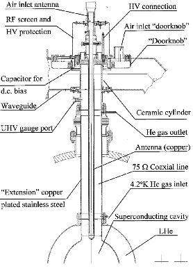
Coaxial lines are prone to multipactor [25], which
can usually be conditioned. Experience at CERN showed, however,
that after some time of operation multipactor reappeared, which
was attributed to re-condensed gas (couplers bridge the full temperature
range from the cavities to room temperature). Applying a positive
DC bias voltage of +2500 V to the inner conductor permanently
suppressed multipactor. The design value for this coupler is a
power transfer of 120 kW under matched conditions. It has been
tested on a cold cavity up to 200 kW cw transferred power, limited
only by field emission in the test cavity, and conditions have
been reached in cold tests, which correspond to 450 kW of transferred
power [26].
5.2.2. Waveguide couplers:
The design developed at Cornell uses ceramic discs in the waveguide
as vacuum seal, the coupling is done directly from the waveguide
to the cut-off tube on the cavity. This window has been tested
in warm tests up to 250 kW traveling wave and 125 kW standing
wave power, in a beam test with a cold cavity a maximum of 155 kW
was transferred to the beam.
5.3. Higher Order Mode (HOM) couplers
Superconducting structures have high Q values also
for the modes excited by the beam. They can harm beam stability
and they can reach amplitudes above breakdown field due to the
long memory of the cavities. The effects of these modes on high
intensity beams, especially their influence on beam halo still
needs to be studied. All storage rings are equipped with higher
order mode couplers, which are usually built as antennas with
an incorporated high pass filter rejecting the fundamental frequency
component. At TRISTAN they work with beam currents of 4*4.5 mA,
giving HOM power of 200 W/coupler, the LEP HOM couplers have been
tested on a cold cavity at 640 MHz up to 0.85 kW per coupler.
For CESR upgrade presently a 5 kW design is being developed, which
was tested with beam on a SC cavity up to 2 kW.
6.1. Big aperture
In NC structures shunt impedance is an important design criterion, leading to small beam apertures. For SC cavities this is less important because of the much higher Q-values. The apertures therefore can be made bigger. In the example of LEP the aperture for the Cu cavities is 100 mm, for the SC cavities 241 mm.
This leads to a much reduced transverse impedance, which scales as the third power of the transverse dimensions. Therefore the problems of beam break up are reduced, the wake fields are smaller, and the alignment tolerances are less tight.
Large apertures help to reduce beam loss, which is
a very stringent condition in high current proton accelerators
because of material activation, less than 1 nA/m/GeV are permitted
[14]
6.2. High gradient, efficiency, and stored energy
SC technology has been shown to work at high gradients in large scale applications. The 144 LEP cavities are running reliably near 6 MV/m at beam currents of 5 to 5.5 mA. CEBAF cavities presently are usable on average up to 7.0 MV/m.
High gradients lower the total impedance, and shorten
the accelerator length. With cavities used in LEP, the gradient
per m of accelerator length including cold to warm transitions,
pumps, bellows, etc. is:
for the Cu system (accelerating cavities only) : 0.9 MV
for the SC system: 3.4 MV
This can be improved by combining more cavities in one cryostat.
For structure cost, it turns out, taking the example of LEP equipment, that the price per MV is about the same for NC and SC RF including the cryogenic investment for a large system.
The RF installation is however much reduced. In LEP
two 1 MW klystrons in the Cu system provide 38 MV, in the SC system
160 MV. The transfer to the beam with 14 mA total current is 0.46
MW in the Cu case, 2 MW in the SC case.
| 10 mA | 100 mA | |
| Cu system | 81 kW / MV | 217 kW / MV |
| SC system | 18 kW / MV | 154 kW / MV |
Table 1: Wall plug power calculated for LEP2 parameters
( 352 MHz)
Proton linacs are under discussion with 1.0 GeV energy and 100 mA beam current. This beam power of 100 MW makes the problem of efficient power transfer into the beam a prime issue. Using numbers from LEP give the wall plug powers shown in table 1 for 10 mA and 100 mA total current for the NC and the SC systems.
This is under the following assumptions:
| stable phase angle : | 20 deg. |
| acc. gradient Cu cavities: | 2.35 MV/m |
| acc. gradient SC cavities: | 6 MV/m |
| cryogenic efficiency: | 225 W/W |
| waveguide losses: | 5 % |
| klystron efficiency: | 65 % |
| static losses of cryostat
(incl. warm gas return): | 180 W/four-cavity module |
For the 100 mA case, the RF power per 4-cell LEP cavity is 940 kW, which could be handled with 2 or 4 couplers per cavity. This is for beta=1 structures, but the arguments are valid for lower beta structures. The actual parameters such as number of cells per cavity and RF frequency have to be optimized.
For pulsed operation the advantage of SC cavities becomes smaller, because the cavity filling time may become an appreciable fraction of the pulse length. The RF power increases accordingly. In the case of ESS this is about 6.3 %, in [14] 14 % are quoted.
The high gradient leads to higher stored energy in
the cavities. This can be an advantage for smaller beam loading
effects and for efficiency. LHC and the CLIC drive beam facility
make use of this.
7.1. Beam loading
SC cavities can not directly replace Cu structures.
There are important differences in beam loading, and especially
the transient behavior in case of RF trips or beam loss needs
attention. Because the unloaded Q values are in the order of 109,
the power couplers have to be strongly overcoupled to provide
optimum power transfer to the beam. For LEP cavities the loaded
Q for 50 mA operation would be QL=4.5 *105.
This leads to big reflections in case of current fluctuations
and strong beam loading effects. In case of RF trips, the peak
reflected power is 4 times the forward power without beam for
a given voltage. In case of a beam loss, the power arriving at
the power coupler would drive the cavities to twice the nominal
accelerating field. A fast RF control is therefore required to
avoid damage.
7.2. Field oscillations
SC cavities are built like large bellows, and they
can mechanically oscillate. The high Q-values make their fields
and phases very sensitive to mechanical vibrations. Experience
at LEP revealed several sources of field oscillations.
7.2.1. Oscillations related to cryogenic conditions.
Field oscillations up to 40% peak-peak have been observed in some
cavities, which can be attenuated by changing the Liquid He level
or the operating pressure in the He tank.
7.2.2. Effects due to Lorentz forces. The SC cavities deform mechanically due to the forces on the walls from the electromagnetic fields. The frequency change resulting from this is proportional to the square of the field amplitude.
Lorentz forces can lead to a coupling between electromagnetic energy in the cavities and mechanical oscillations. It can be shown, that if the cavities are tuned to frequencies below their resonance, the system becomes unstable and starts to oscillate [27] at a mechanical resonance of the cavity. In LEP operation this occurs in the presence of beam, because the tuning system compensates the effect of the beam by detuning the cavities towards the dangerous direction. This problem is solved for the time being in LEP by detuning the cavities, such that at maximum current and maximum field, the cavities are driven at or near their resonance.
In pulsed applications, Lorentz force detuning causes a movement of the cavity walls in each RF pulse, which can continue during the whole length of the pulse. Phasing schemes have been invented [28] to solve this problem, however, their practical feasibility with several cavities driven in parallel from the same RF source, needs to be demonstrated.
In LEP the residual field oscillations can still
be as high as 10%, a fast RF feedback on the vector sum is being
implemented, to keep the fields of each group of 8 cavities constant.
Quite sophisticated technology, requiring heavy infrastructure
and skilled personnel is required for production and also for
maintenance, including cleaning facilities, chemistry, clean room
etc. This and the operation at cryogenic temperatures, makes turn-around
time in development long and even minor repairs can become quite
time consuming. Extreme discipline and professionalism is required.
Fast repair, especially of activated material is certainly difficult
with techniques presently available. The e-folding time for decay
of activated Nb is Å1 month, as compared to 13 hrs. in Cu.
It has been shown that SC RF structures are available for reliable operation in accelerators. Nowadays, gradients of around 6 MV/m have been achieved for high beta applications. Structures for heavy ion accelerators have been in continuous use for several years. All the other components required have been or are being developed for high current circular accelerators: RF power couplers have been used to transfer up to 250 kW via a SC cavity and fields in couplers equivalent of 400 kW power transfer have been achieved, and development is going on in many laboratories. HOM couplers have been tested in storage rings up to several kW power.
RF superconductivity bears the potential of substantial savings in investment, especially infrastructure, and also in operating cost of the RF system due the higher gradient and the more efficient power transfer to the beam. The large beam aperture is advantageous to both reduced beam losses and transverse impedance.
The know how and the technical infrastructure needed
for development work and follow-up of production are available
in several large laboratories today.
[1] M.S. McAshan, K. Mittag, H.A. Schwettman, L.R. Suelzle, J.P. Turneaure, Appl. Phys. lett. 22, p. 605 (1973).
[2] L.M. Bollinger, NIM B40 (1989), p.884.
[3] B. Cauvinet al., 6th. ws. on RF SC, CEBAF 1993 p. 1020.
[4] J. Auerhammer, H. Genz, H.D. Gräf, V. Huck, C. Lüttge, A. Richter, T. Rietdorf, P. Schardt, E. Spamer, K. Rühl, A. Staschek, F. Thomas, O. Titze, J. Töpper, H. Weise, 5. ws.on RF SC, DESY 1991, DESY M-92-01 (1992), p. 110.
[5] S. Noguchi et al., , 4th. EPAC, London (1994), p. 1891.
[6] B. Dwersteg, G. Kreps, A. Matheisen, W.D. Möller, C. Müller, D. Proch, D. Renken, J. Sekutowicz, EPAC, London (1994), p. 1039.
[7] C. Reece et al., "Beam Test of a Superconducting Cavity for the CESR Luminosity Upgrade", PAC 1995, Dallas, p. 1512.
[8] R. Brinkmann, EPAC, London (1994), p. 363.
[9] H. Padamsee et al., EPAC, London (1994), p. 2048.
[10] S. Kurokawa, EPAC, London (1994), p. 473.
[11] L. Thorndahl, This conference.
[12] "The Large Hadron Collider", CERN/AC/95-05(LHC), p. 60.
[13] "Outline Design of the European Spallation Neutron Source", ed. I.S.K. Gardner, H. Lengeler, G.H. Rees, ESS-95-30-M.
[14] R.A. Jameson, "Discussion of Superconducting and Room Temperature High-Intensity Ion Linacs", EPAC 1996.
[15] K.C.D. Chan, et al., 7th. ws on RF superconductivity, (1995), Saclay, p. 623.
[16] C. Rubbia, J.A. Rubio, CERN/LHC/96-11 (EET).
[17] H. Piel, CAS, Oxford 1985, CERN 87-03, p. 736.
[18] Ph. Lebrun, CERN LHC/96-05.
[19] U. Wagner, CERN/LHC, private communication.
[20] H. Padamsee, K.W. Shepard, R. Sundelin, Annu. Rev. Nucl. Part. Sci (1993), 43, p. 635.
[21] D.W. Storm, 6th. workshop on RF superconductivity, CEBAF, (1993), p. 216.
[22] J.R. Delayen, C.L. Bohn, C.T. Roche, Proc, 1990 Lin. Acc. Conf., Albuquerque, LA 12004-C, p. 85.
[23] J.R. Delayen, C.L. Bohn, C.T. Roche, Proc, 1990 Lin. Acc. Conf. Albuquerque, LA 12004-C, p. 82.
[24] E. Chiaveri, "Large Scale Industrial Production of Superconducting Cavities", EPAC 1996, Sitges.
[25] E. Somersalo, P. Ylä-Oijala, R. Nevanlinna, D. Proch, Proc. 1995 PAC Dallas, p. 500.
[26] H.P. Kindermann et al., "Status of Power Couplers for Superconducting Cavities at CERN", EPAC 96, Sitges.
[27] D. Boussard, P. Brown, J. Tückmantel, "Electroacoustical Oscillations in the LEP SC Cavities", EPAC 1996, Sitges.
[28] A. Mosnier, J.M. Tessier, Proc. 4th European
Part. Acc. Conf. EPAC, London 1994, p. 1989.