This paper reviews the work performed by the International
Linear Collider Technical Review Committee to examine and compare
the designs and R&D status of the various e+e linear
colliders currently under study in the world. The paper summarizes
the highlights of the report issued in December 1995 and, where
applicable, indicates some of the changes that have occurred since
its publication.
In June 1994 at EPAC 94 in London, the International Council of the Interlaboratory Collaboration of R&D Towards TeV-scale Electron-Positron Linear Colliders created an International Technical Review Committee (TRC) consisting of close to sixty scientists, and charged it with producing a report bringing together in one document all the e+e linear collider designs and technologies in the world. The machines to be studied and compared were to start at c.m. energies of 500 GeV and have expansion capability to 1 TeV and above. The report [1] was completed in December 1995. The author of this paper was Chair of the TRC, T. Weiland represented the Secretariat, and E. Mitchell at SLAC was in charge of production. The TRC report is 186 pages long and only some of the highlights can be summarized here.
The particle physics community has been greatly interested
in such an accelerator for some years, and, if anything, this
interest has grown with the decision to proceed with the LHC.
Indeed, these two machines are highly complementary in what they
can contribute to the field. The linear collider will be a precision
tool to study ![]() production at threshold and
above. If the Higgs and/or supersymmetric particles exist, the
linear collider will be instrumental in discovering and/or studying
them. If none of these particles exist, the machine will make
it possible to explore other mechanisms to explain electroweak
symmetry breaking. These are some of the most burning issues to
be elucidated in the next few years. The e+e linear
collider also has the potential of producing exciting physics
from ee, e and collisions, and of involving other applications
such as FEL's and other technologies.
production at threshold and
above. If the Higgs and/or supersymmetric particles exist, the
linear collider will be instrumental in discovering and/or studying
them. If none of these particles exist, the machine will make
it possible to explore other mechanisms to explain electroweak
symmetry breaking. These are some of the most burning issues to
be elucidated in the next few years. The e+e linear
collider also has the potential of producing exciting physics
from ee, e and collisions, and of involving other applications
such as FEL's and other technologies.
The TRC report consists of six chapters. The first
chapter is a description of six machines at 500 GeV c.m. energy:
TESLA, SBLC, JLC (S-, C- and X-band), NLC, VLEPP and CLIC. The
second chapter includes the reports of six working groups respectively
describing and comparing Injection Systems, Damping Ring and Compression
Systems, Linac Technology, Beam Dynamics, Beam Delivery and Experimentation
for the various machines. The third chapter describes methods
proposed for each machine to upgrade their c.m. energies to 1
TeV and to obtain ee, e and collisions. Chapter 4 describes on-going
experiments and test facilities, Chapter 5 discusses present
and future areas of collaboration, and Chapter 6 presents conclusions.
Given that this conference is devoted primarily to linacs, the
emphasis in this paper is focused on this subject.
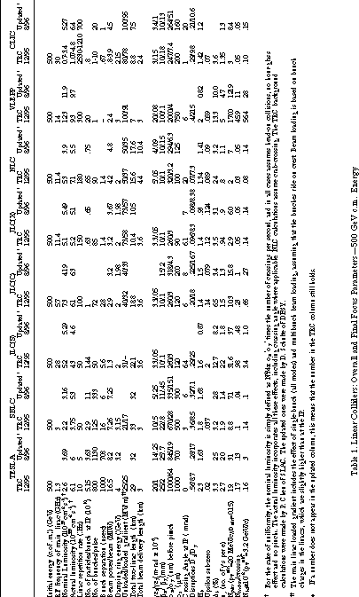
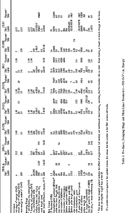
Overall and final focus parameters for all the machines
are shown in Table 1 and those for pre-linacs, damping rings and
main linacs are given in Table 2. For each machine, there are
two columns: the first one gives the numbers listed in the TRC
report of December 1995, the second one shows new numbers where
an update has taken place as of August 1996. As can be seen, all
the machine designs have now reached luminosities above 1033cm-2sec-1
which with the exception of VLEPP, are obtained by using many
bunches per rf pulse. The main linacs which operate at the lower
rf frequencies have the lowest gradients and are therefore the
longest. For all machines, the ultimate and most challenging specification
is the y* at
the IP which ranges between 19 and 3 nm. For reference, the FFTB
at SLAC at 50 GeV has so far reached a y of 70 nm.
Let us now characterize the various machines by dividing them
into four groups in order of ascending rf frequency: 1) TESLA,
2) SBLC, JLC(S), JLC(C), 3) JLC(X), NLC (with its future
TBNLC option), VLEPP, and 4) CLIC. The building blocks of the
various main linac "power units" for these machines
are shown in Fig. 1. The design, engineering, mass production
and cost of these "power units" are crucial to the success
of whichever linear collider ultimately gets selected and built
because of the large quantities of identical components involved.
TESLA (Group 1)
This machine is in a category by itself because it is the only one that uses superconducting accelerator sections for the main linacs. The rf frequency is the lowest (1.3 GHz) and the beam aperture is the largest (2a = 7 cm). All the characteristics of TESLA result from these basic features. The advantages are that the rf pulse is long, the bunch spacing is wide (708 ns), the transverse wakefields [which for single bunches vary roughly as -3(a/)-2.2] are weakest, and corresponding alignment tolerances are loosest (by at least a factor of 5 for multibunches). As a result, emittance growth will be easiest to control. Ground motion effects may be compensated by fast feedback controls and by bunch-to-bunch steering at the end of each linac. Note, however, that the decision to reduce the repetition rate from 10 to 5 Hz has forced y* down from 64 to 19 nm to conserve luminosity. The biggest challenge for TESLA is to perfect the rf superconducting technology to the point where accelerating gradients of 25 MV/m can be attained reliably with Q0's of at least 5x10⁹, and that costs can be made affordable. The main linacs consist of 616 power units, each involving a pulsed modulator supplying an 8 MW peak power klystron which in turn drives 32 one-meter long superconducting structures in four long cryostats, incorporating HOM couplers and quadrupoles.
Related requirements are the compensation of the
mechanical cavity detuning due to the Lorentz force, the absolute
need to suppress field emission to avoid heat losses and captured
dark current, the construction of a variable coupler, and alignment
of components within the cryostats. The electron bunch train can
be produced from a laser-driven gun but the positron bunch train
is too intense for a conventional target to survive. Hence, the
intent is to shoot the spent e beam after the IP through
an undulator to produce 's which then produce positrons in a thin
rotating target. The 3.2 GeV damping rings (often called dog-bones
because of their shape) must be designed to accept and damp each
long train of bunches (240 km) in a "compressed" circumference
(17 km). Finally, since the main linacs are already very long
(32 km), the expandability to 1 TeV c.m. energy will preferably
be achieved, at least in part, by an increase in gradient (say
40 MV/m). Such a gradient will require an additional 25%
increase in length to 40 km. The desired luminosity at 1 TeV
can be reached with a y* of 6.5 nm and a
B of 2.5%.
SBLC, JLC(S) and JLC(C) (Group 2)
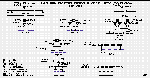
SBLC and its close cousin, JLC(S), benefit from the most widespread and proven technology developed at SLC and elsewhere for many years. Roughly speaking, their main linacs are equivalent to 7-10 SLAC linacs. SBLC has the next-to-largest y* (15 nm) after TESLA and gets its luminosity at 50 Hz repetition rate with 333 bunches per pulse spaced 6 ns apart and 1.1x10¹⁰ particles per bunch. JLC(S) gets its luminosity with a y* of 3 nm, 50 Hz, 50 bunches spaced 5.6 ns apart and 1.44x10¹⁰ particles per bunch. For the 500 GeV c.m. case, SBLC does not use pulse compression whereas JLC(S) uses SLED I. The respective power units are shown in Fig.1. Because of multibunch operation, the accelerator structures are designed to detune and damp transverse wakefields. SBLC has tested 6 m-long sections with two sets of higher-order mode couplers along their length, which can also be used as pick-ups to align the sections by minimizing beam induced fields. Sputtering of a 20 m-thick low conductivity material onto the disk edges is also being used to differentially reduce the Q of undesirable modes by a factor of 5 without affecting the fundamental mode Q by more than 5%. Initial alignment tolerances are on the order of 100 m and sections must be mounted on girders to within a tolerance of about 30 m rms. JLC(S) uses 3.6 m-long sections similar to the SLC. The electron and positron sources for SBLC are similar to TESLA's, those for JLC(S) resemble those of the SLC but have not yet been designed in detail. The energies of the damping rings are respectively 3.15 and 1.98 GeV. Extension to 1 TeV c.m. for SBLC is envisaged by doubling the number of klystrons and adding pulse compressors to double the gradient within the original machine length. No upgrade option to 1 TeV has been offered for JLC(S).
JLC(C) was not considered in any detail in the TRC
report because experimental work at C-band had not yet started
at KEK at the time. Since then, an active R&D program has
been launched on the rf components, including a 50 MW peak power
klystron, a choke-mode type, 1.8 m-long accelerator structure
and a multicell coupled cavity system for a short SLED II pulse
compressor. The choke-mode structure eliminates the multibunch
wakefield problem and has an alignment tolerance of 30 m. The
beam characteristics are similar to those of the X-band design,
except for a longer bunch length. Extension to 1 TeV c.m.
energy would be obtained by doubling the klystron output power
to 100 MW and increasing the length of the main linacs by 40%.
JLC(X), NLC and VLEPP (Group 3)
Although VLEPP is designed for 14 GHz while JLC(X) and NLC use 11.4 GHz for their main linacs, these three machines can be described in a single group because of their technological similarities. JLC(X) and NLC have similar luminosities, repetition rates, numbers of bunches per pulse and charges per bunch. The y* at the IP for JLC(X) is 3 nm whereas that for NLC is about 6 nm, but this difference does not arise from any fundamental differences in design. There is also a slight difference in z*, and crab-crossing at the IP is proposed for NLC whereas it may not be needed for JLC(X). The main difference between the two machines appears in their main linac gradients (57 MV/m for JLC(X) vs. 35 MV/m for NLC) and results from the differences in their power unit designs (see Fig.1). JLC(X) proposes to use the delay line distribution system (DLDS) whereas NLC uses SLED II, possibly to be replaced by the more efficient binary pulse compression (BPC) at a later date. The NLC klystron is planned to be a 50 MW tube (later to be upgraded to 72 MW) with permanent periodic magnet (PPM) focusing, which is currently being tested successfully at SLAC. The JLC klystron will probably be similar. R&D toward efficient and simplified modulators is crucial for eventual economy of electric power and manufacturing costs. For accelerator structures, NLC will use sections in which transverse deflecting modes are both detuned (within a Gaussian distribution) and damped to a Q of about 1000 (by coupling to four external parallel rectangular matched manifolds). First tests of this so-called DDS structure indicate that its fabrication can be achieved successfully by diffusion bonding of cups with cell-to-cell alignment better than 4 m. It is likely that JLC(X) will use very similar sections, albeit 1.3 m long. The electron bunch trains for both machines will be produced by laser-driven photocathode guns, and the positrons by improved SLC-type sources, in combination with various L-band and/or S-band pre-accelerators. The pre-damping and damping ring energies are all at about 2 GeV.
VLEPP is based on a design with a single bunch per
rf pulse which does away with the multibunch wakefield problem.
This design must get its luminosity from a much greater charge
per bunch (2x10¹¹particles) which unfortunately leads
to very high backgrounds. The VLEPP rf power unit can also be
seen in Fig.1. In theory, it leads to a loaded gradient of 91
MV/m. For extension to 1 TeV c.m., JLC(X) and VLEPP would
be doubled in length whereas NLC would get there by a 20% increase
in length (built-in from the beginning), a doubling in the number
of klystrons and an increase in their power from 50 to 72 MW.
Alternatively, if the TBNLC (two-beam) technology based on drive
beams accelerated by induction linacs were to become successful
in the future, the NLC could have its array of klystrons, modulators
and rf pulse compressors replaced by 64 sequential drivers, each
300 m-long (see Fig.1) with transfer structures to supply the
individual linac structures with the desired rf pulses.
CLIC (Group 4)
CLIC occupies a unique position in parameter space.
The IP spots are similar to those in Group 3. The machine is characterized
by the highest linac rf frequency, highest dark current capture
field and potentially highest gradient. It requires many innovations,
has the strongest wakefields, and therefore the tightest fabrication
and alignment tolerances. The rf power is generated by an intense
drive beam, accelerated by LEP-type superconducting structures,
which induces the power in special transfer structures. The problem
of producing thousands of klystrons, modulators and rf pulse compressors
is replaced by having to create two high-current drive beams with
a bunch time structure capable of generating rectangular rf pulses
at 30 GHz. The problem of producing these drive beams and then
conserving their phase space qualities along the full length of
the linacs is a major challenge. An advantage of the CLIC two-beam
scheme is that it allows all the components to be housed in one
tunnel. The front end of the main e+e beam generation
is analogous to the front end of the SLC. A number of design features
of these drive and main beams remain to be elucidated, particularly
for 20 bunches/pulse operation which has recently been chosen
to bring up the luminosity within the range of the other machines.
For 1 TeV c.m. energy, both the drive and main linacs would be
doubled in length.
Because of lack of space, there are many topics in the TRC report that cannot be reviewed in this paper. Fortunately, many other papers at this conference deal with recent important linear collider developments. Worldwide investment in this field is spawning a vast amount of new knowledge and technologies. The SLC at SLAC and the new test facilities at DESY, KEK, SLAC, BINP, CERN and LBNL are contributing to an explosion of R&D. New laser-driven photocathode electron sources with 80% polarization have become a reality, and new positron sources and pre-linacs are undergoing design. The very small emittances that must be created by the damping rings and preserved through the bunch compressors, main linacs, beam delivery systems and final foci are giving rise to new ideas about instrumentation, alignment, stability, collimation and beam containment. New insights are being gained into beam dynamics (dispersion-free and wakefield-free steering, transient beam loading) and into the important field of ground vibrations over a wide range of frequencies (102 to 10+2Hz) and coherence lengths. Finally, a whole new approach towards design for manufacturing (DFM) to decrease mass production costs while preserving tolerances, cleanliness to avoid field emission and dark current, high vacuum conditions, and above all, reliability of operation, is being introduced into the field of accelerator fabrication and pricing.
Work supported by Department of Energy contract DE-AC03-76SF00515.
[1] "International Linear Collider Technical
Review Committee Report," SLAC-R-95-471, (1995)