A sweep plate emittance scanner for use with high power, continuous wave (CW) beams has been designed, fabricated and commissioned at Northrop Grumman. The design is capable of scanning beams of up to 20 kW beam power with a spot diameter as small as 2 cm. The scanner pod is mounted on a ball screw driven linear bearing table that is driven through the beam by a stepper motor at velocities up to 30 cm/sec.
This paper presents the thermo-mechanical analysis of the pod moving through a gaussian beam and the details of the mechanical design of the pod and motion system. Analyses to determine scanner cooling schemes and structural materials are presented.
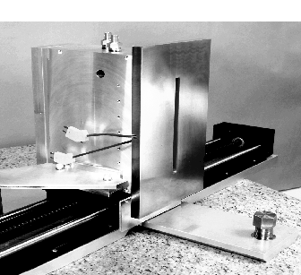
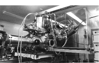
The emittance scanner system was designed at Northrop Grumman in 1994 as a tool for CW ion source development. The first scanner pod (see Fig. 1) was designed for beams up to 100 keV and 200 ma. The complete system consists of the pod, the pod drive system, a vacuum enclosure, vacuum system, beam dump, and data acquisition and control system (see Fig. 2). The scanner is an Allison type sweep plate scanner [1] with defining slits at the entrance and the exit of the sweep plate region (see Fig. 3).
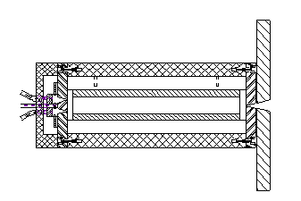
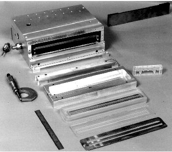
This pod incorporates a dual slit at the exit of the sweep region to facilitate energy resolution. Each slit is formed by a pair of knife edges (blades) adjusted to achieve a gap of .025 mm with a tolerance of +/- .0025 mm. The slits facing the incoming beam pose the biggest problem in the design because they scrape a large amount of beam at high power density. The transient deflection of these knife edges under thermal load must not change the gap during the scan time by more than .0025 mm. To protect the bulk of the upstream blades from the beam, an armor plate that is both mechanically and thermally isolated from the scanner body is used. The function of this plate is simply to absorb the beam power without exceeding the thermal stress limits of the material. On the opposite end of the scanner are the dual slits. Since the thermal load at this point is negligible, these blades are made from 7075 aluminum. Once through this set of slits the beam enters the collector assembly. This consists of a suppresser electrode followed by a pair of Faraday cups, one behind each slit. Figure 4 shows a view of the dis-assembled pod looking from the collector end.
The scanner is operated by driving the pod through the beam using a stepper motor drive system that correlates position with time. As the scanner traverses the beam, thin ribbons of beam are admitted through the .0025 mm front slit. At the same time the voltage applied between the deflection plates is rapidly swept, causing the beam to sweep across the rear apertures. The current measured in the Faraday cups is then correlated with the deflection voltage and the position to determine the phase space of the beam. The CW scanner system is unique in that the voltage on the deflection plates is varied at high frequency allowing the pod to move at up to 30 cm/sec while gathering the complete data set for phase space reconstruction [2].
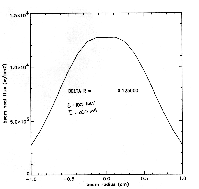
The primary areas for concern in the design of the scanner pod were the stability of the .025 mm aperture at the entrance to the pod, and the survivability of the armor plate which takes the bulk of the thermal loading. Several 2-D and 3-D FEA models of the armor and knife edge were constructed using ANSYS to address these concerns. The beam was modeled as a three dimensional gaussian beam with a total power of 20 kW and a 2s diameter of 2 cm. The analysis was run using only the core 2s (17.4 kW total power) but the remaining 2.6 kW in the outer edges of the beam should have negligible effect on the results shown here. Figure 5 shows a 2-D plot through the center of the power density profile for the 2 cm diameter beam which peaks at 12.7 kW/cm2. This 3-D loading was applied in an ANSYS finite element
transient analysis. An external program generated the ANSYS load step commands based on the pod speed.
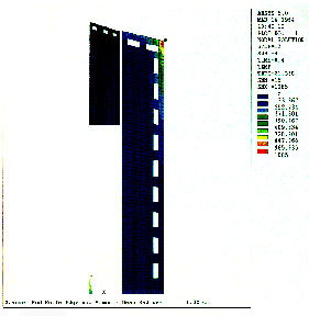
The first area of analysis was to evaluate candidate materials and cooling schemes through a series of 2-D scoping runs. Figure 6 shows the results of a 2-D run for a copper armor plate and knife edge with an elaborate array of cooling passages. Figure 7 shows results for a 3-D
analysis done on solid components (no cooling) with the same materials, the same pod speed of 20 cm/sec, and the same
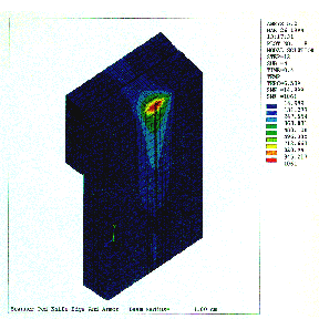
time step. Comparing the results it can be seen that the peak temperatures are lower for the case with no cooling than for the case with cooling. This is explained by the time scale of the transient. At a speed of 20 cm/sec, the pod is exposed to the beam for a total of 0.86 seconds and no point is exposed for more than 0.10 seconds. On this time scale, the coolant film represents a lower conductivity boundary when compared to solid copper. To further lower the peak temperatures, the translation velocity was increased to 30 cm/sec. Figure 8 shows the corresponding output. As a result of this analysis, the design incorporates water cooled chill blocks that are mechanically attached to the pod housing and to the back side of the armor plate to remove the heat between scans.
Glidcop® Al-15 was chosen for the armor plate. The peak stress of 10200 psi at 877º C is well below the yield stress of 45000 psi for Glidcop® but too high for pure copper. We do, however expect that mud cracking may take place over many hours of operation at peak beam power and therefore have made replacement of the armor very straight forward.
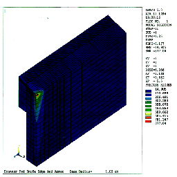
The second area of analysis focused on the blade deflection during a scan. Both Glidcop® Al -15 and the molybdenum alloy TZM were considered in the analysis. The results show that although the TZM blade reaches the considerably higher temperature of 284º C versus 163º C for the Glidcop®, the much lower thermal expansion coefficient and reduced thermal conductivity of TZM make it superior to the Glidcop®. Figure 9 shows the Glidcop® and TZM deflection data. The time step corresponds to the point when
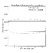
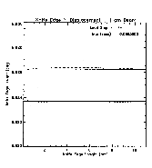
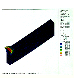
the beam has just cleared the aperture and the last moment when the requirement for a gap of .025 +/-.0025 mm exists. The Glidcop® gap has changed by +/-.006 mm in the area of interest (1 cm radius) while the TZM blade gap has changed by less than +/-.001 mm. In both cases the character of the deflection reflects rapid thermal expansion in the area of the beam core. This causes closing of the gap in that region and associated high compressive stress that leads to bending of the blade and opening of the gap away from the beam core (see fig. 10). In both cases the maximum deflection of the blades occurs well after the scan is complete and the heat soaks into the bulk material.
TZM was chosen in favor of pure molybdenum because of its somewhat better ductility and improved machining characteristics that are important when manufacturing the long straight knife edges.
The CW emittance scanner has been commissioned and utilized in applications with CW beam power up to 1 kW. Most recently, the scanner has been used to commission a 40 keV, 10 ma H- injector [3]. A second scanner pod of the same design but for beam energies up to 2 MeV is in fabrication at Northrop Grumman. The new pod will be used to commission a 2 MeV, 10 ma CW tandem accelerator in late 1996 [4] that will require the pod to perform to the full design levels.
[1] Paul W. Allison, Joseph D. Sherman, and David B. Holtkamp, "An Emittance Scanner for Intense Low-Energy Ion Beams," IEEE Trans. Nucl. Sci. NS-30, No.4, 2204 (1983).
[2] T.W. Debiak, Y. Ng, and J. Sredniawski, "A Sweep Plate Emittance Scanner for High-Power Ion Beams," These Proceedings.
[3] S.T. Melnychuk, T.W. Debiak, Y. Ng, J. Rathke, R. Schmidt, J. Sredniawski, B. Milton, and T. Kuo, "Commissioning of the 40 keV Injector for a Contraband Detection System Proof-of-Principle Device," These Proceedings.
[4] J. Sredniawski, T.W. Debiak, E. Kamykowski, J. Rathke, B. Milton, J. Rogers, P. Schmor, G Stanford, and J. Brondo "A Contraband Detection System Proof-of-Principle Device Using Electrostatic Acceleration," These Proceedings.